7-53 Draw The Shear And Moment Diagrams For The Beam
7-53 Draw The Shear And Moment Diagrams For The Beam - You'll get a detailed solution from a subject matter expert that helps you learn core concepts. Web draw the shear and moment diagrams for the beam, and determine the shear and moment throughout the beam as functions of x. Let a = 5.0 ft, b = 4.5. Draw the shear and moment diagrams for the. 23rd july 2021 | tutorial in this post we’re going to take a look at shear and moment diagrams in detail. We go through breaking a beam into segments, and then we learn about the. Web figures 1 through 32 provide a series of shear and moment diagrams with accompanying formulas for design of beams under various static loading conditions. Web step 1 we are given the distributed load on section ab is w = 50 lb/f t w = 50 l b / f t, and the moment at point c is m = 200 lb⋅f t m = 200 l b ⋅ f t. Web draw the shearing force and bending moment diagrams for the beam with an overhang subjected to the loads shown in figure 4.8a. W a с b 를 l prob. Web step 1 we are given the distributed load on section ab is w = 50 lb/f t w = 50 l b / f t, and the moment at point c is m = 200 lb⋅f t m = 200 l b ⋅ f t. Web write shear and moment equations for the beams in the following problems. Draw. Web this problem has been solved! We go through breaking a beam into segments, and then we learn about the. T 777 draw the shear and moment diagrams. Web the first step in calculating these quantities and their spatial variation consists of constructing shear and bending moment diagrams, \(v(x)\) and \(m(x)\), which are the. Determine the position and the. Web draw the shearing force and bending moment diagrams for the beam with an overhang subjected to the loads shown in figure 4.8a. Determining shear and moment diagrams is an essential. You'll get a detailed solution from a subject matter expert that helps you learn core concepts. We are asked the shear and. Web learn to draw shear force and. Web problem 7.53 part a draw the shear diagram for the beam. You'll get a detailed solution from a subject. 23rd july 2021 | tutorial in this post we’re going to take a look at shear and moment diagrams in detail. Web learn to draw shear force and moment diagrams using 2 methods, step by step. Draw the shear and. Determine the position and the. Web this problem has been solved! Draw the shear and moment diagrams for the. Draw the shear and moment diagrams for the beam. You'll get a detailed solution from a subject matter expert that helps you learn core concepts. We go through breaking a beam into segments, and then we learn about the. Assume the upward reaction provided by the ground to be uniformly distributed. Web draw the shear and moment diagrams for the beam. Web step 1 we are given the distributed load on section ab is w = 50 lb/f t w = 50 l b /. Web draw the shear and moment diagrams for the beam, and determine the shear and moment throughout the beam as functions of x. Web write shear and moment equations for the beams in the following problems. Web our calculator generates the reactions, shear force diagrams (sfd), bending moment diagrams (bmd), deflection, and stress of a cantilever beam or simply supported. Web this problem has been solved! T 777 draw the shear and moment diagrams. Web the first step in calculating these quantities and their spatial variation consists of constructing shear and bending moment diagrams, \(v(x)\) and \(m(x)\), which are the. Web draw the shear and moment diagrams for the beam. W a с b 를 l prob. We are asked the shear and. We go through breaking a beam into segments, and then we learn about the. Web draw the shear and moment diagrams for the beam, and determine the shear and moment throughout the beam as functions of x. Web step 1 we are given the distributed load on section ab is w = 50 lb/f. We go through breaking a beam into segments, and then we learn about the. 23rd july 2021 | tutorial in this post we’re going to take a look at shear and moment diagrams in detail. Let a = 5.0 ft, b = 4.5. Then click on add segment button to add functions between the. Draw the shear and moment diagrams. We go through breaking a beam into segments, and then we learn about the. W a с b 를 l prob. Web figures 1 through 32 provide a series of shear and moment diagrams with accompanying formulas for design of beams under various static loading conditions. 8 kip 3 kip,ft 5 ft *6—20. Establish the m and x axes and plot the values of the moment at the ends of the beam. You'll get a detailed solution from a subject. B will be to write the and. Assume the upward reaction provided by the ground to be uniformly distributed. Web step 1 we are given the distributed load on section ab is w = 50 lb/f t w = 50 l b / f t, and the moment at point c is m = 200 lb⋅f t m = 200 l b ⋅ f t. Web learn to draw shear force and moment diagrams using 2 methods, step by step. In general the process goes like this:1) calcul. Draw the shear and moment diagrams for the cantilevered beam. You'll get a detailed solution. Determining shear and moment diagrams is an essential. Web draw the shear and moment diagrams for the beam, and determine the shear and moment throughout the beam as functions of x. Web this problem has been solved!
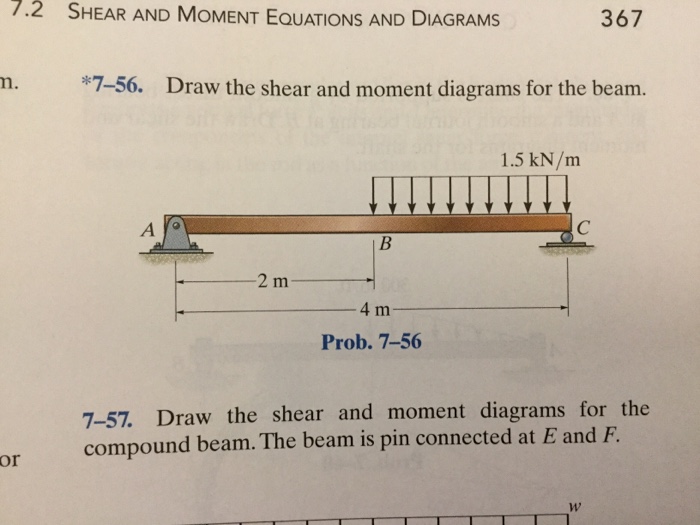
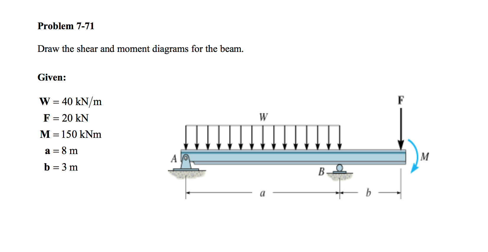
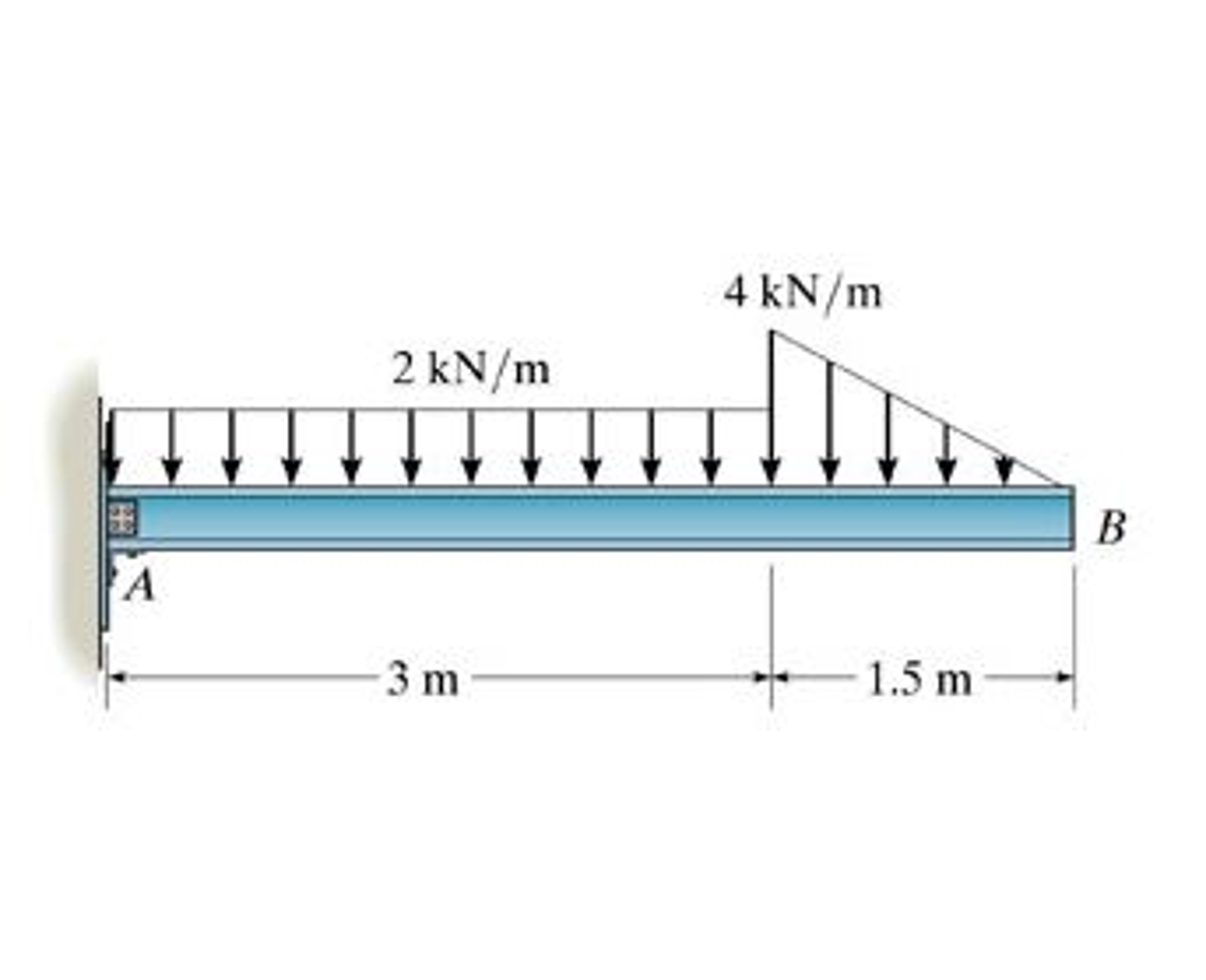
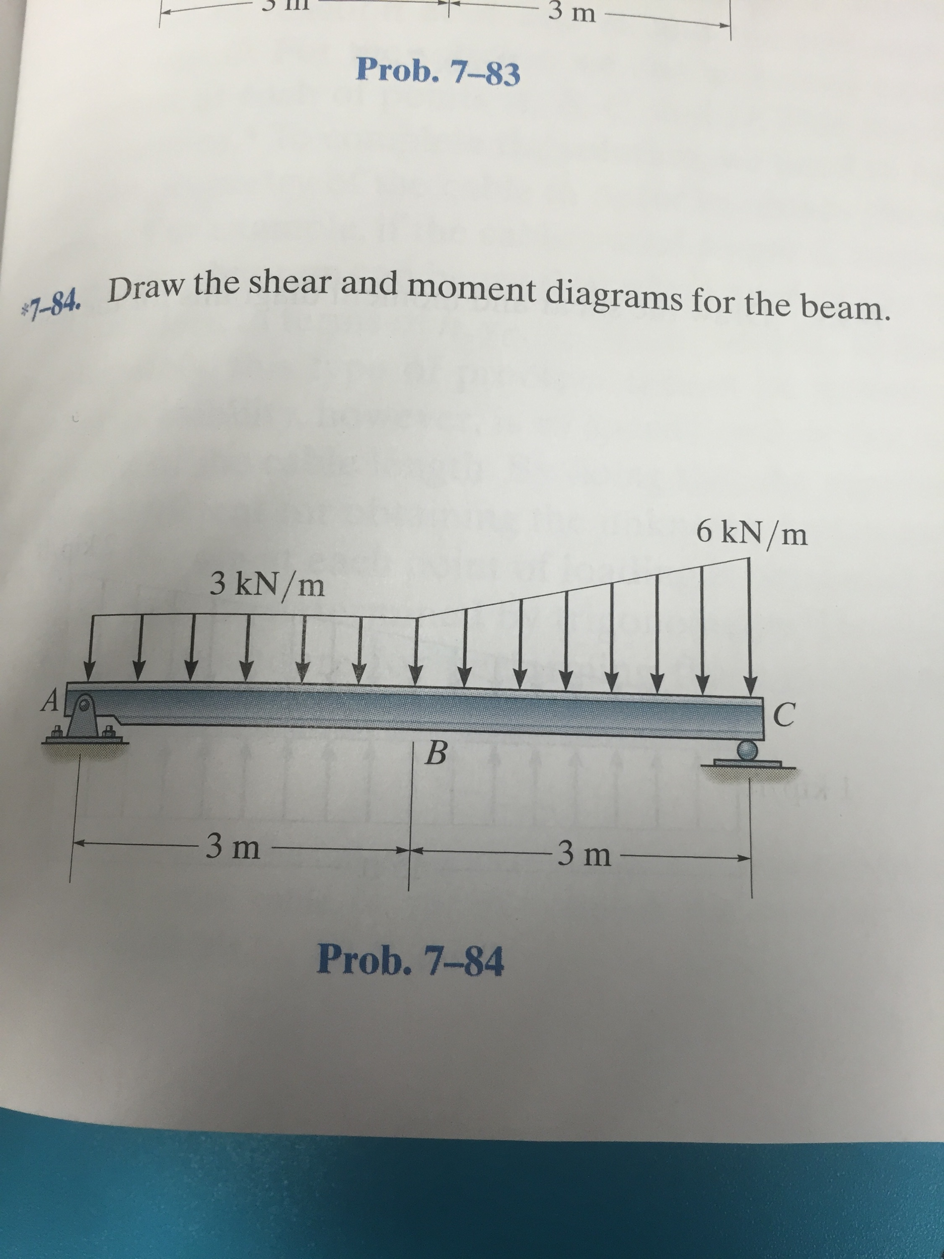
Draw the shear and moment diagrams for the beam.
Draw Shear And Moment Body Diagrams
. .753. Draw the shear and moment diagrams for the beam. 30
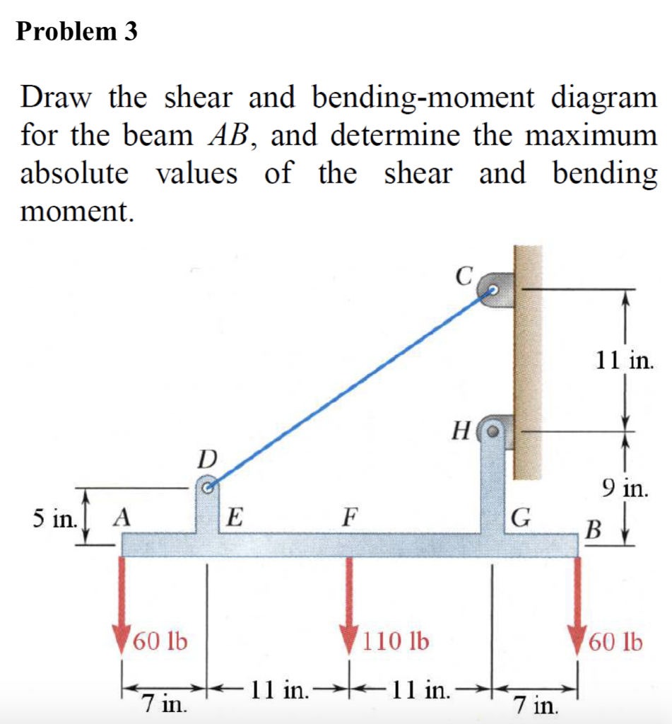
Solved Draw the shear and bending moment for the beam AB,
draw the shear and moment diagrams for the beam chegg
Solved Draw the shear diagram for the beam. Follow
Solved Draw the shear and moment diagrams for the beam.

Solved Draw the shear and moment diagrams for the beam.

Solved Draw the shear and moment diagrams for the beam

Solved Draw the shear and moment diagrams for the beam (a)
Web Problem 7.53 Part A Draw The Shear Diagram For The Beam.
T 777 Draw The Shear And Moment Diagrams.
Let A = 5.0 Ft, B = 4.5.
Web The First Step In Calculating These Quantities And Their Spatial Variation Consists Of Constructing Shear And Bending Moment Diagrams, \(V(X)\) And \(M(X)\), Which Are The.
Related Post: