Draw Logic Gates
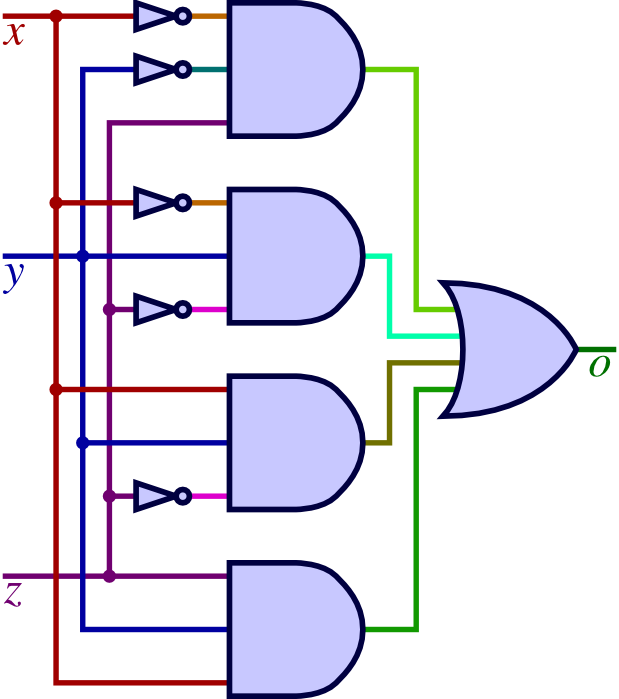
Draw Logic Gates - Web how to draw a logic gate using creately? Visual paradigm's logic diagram tool features a handy diagram editor that allows you to draw logic diagrams swiftly. The smallest circuit is a chain of 2 logic gates. Web a logic gate is a digital gate that allows data to be transferred. The following types of logic gates are commonly used: Logic gates, on the other hand, govern the flow of information based on a set of rules. The not gate is also known as an inverter because the output is the exact opposite of the input. Logic gates are used to carry out logical operations on single or multiple binary inputs and give one binary output. Web need to draw logic gate diagrams? Select one logic gate diagram template to edit on it or click the [+] sign to start from scratch. And gate, or gate, xor gate, nand gate, nor gate, xnor gate, and not gate. This electronics video provides a basic introduction into logic gates, truth tables, and simplifying boolean algebra expressions. The not gate is also known as an inverter because the output is the exact opposite of the input. Web how to draw a logic gate using creately?. Web a logic gate is a digital gate that allows data to be transferred. Web start building now features build and simulate your own circuits with logigator, a simple yet powerful online tool. Navigate to [new]> [electrical engineering]> [circuits and logic] step 3: Since the inputs and outputs of logic gates are just wires carrying on/off signals, logic gates can. Performance logigators' editor can handle even the largest projects with ease thanks to webassembly and webgl. Web a logic gate is a digital gate that allows data to be transferred. The truth table is used to show the logic gate function. An example is also shown in figure 1.3. An example is also shown in figure 2.3. First you will need to learn the shapes/symbols used to draw the four main logic gates: Web dive into the world of logic circuits for free! Visual paradigm's logic diagram tool features a handy diagram editor that allows you to draw logic diagrams swiftly. The logic circuit in the figure has three inputs, labeled a, b, and c. A.b can. Web the basic logic gates are classified into seven types: Web since the inputs and outputs of logic gates are just wires carrying on/off signals, logic gates can be wired together by connecting outputs from some gates to inputs of other gates. It discusses logic gates s. We call that a logic circuit. Web 21k views 2 years ago office. And, or, xor, not, nand, nor and xnor. The following illustration and table show the circuit symbol and logic combinations for an and gate. There are seven basic logic gates: The result is a logic circuit. Computers perform more than simple boolean logic operations on input data, and they typically output more than a single binary digit. Web the basic logic gates are classified into seven types: Hope you will learn something new, don't forget to subscribe. Performance logigators' editor can handle even the largest projects with ease thanks to webassembly and webgl. In this video, i'm going to show how to use a free online diagramming tool diagrams.net (draw.io). An example is also shown in figure. Every logic gate has a representation symbol. When drawing a truth table, the binary values 0 and 1 are used. First you will need to learn the shapes/symbols used to draw the four main logic gates: Web since the inputs and outputs of logic gates are just wires carrying on/off signals, logic gates can be wired together by connecting outputs. Web since the inputs and outputs of logic gates are just wires carrying on/off signals, logic gates can be wired together by connecting outputs from some gates to inputs of other gates. Web the basic logic gates are classified into seven types: When drawing a truth table, the binary values 0 and 1 are used. Circuits enables computers to do. Logic gates, on the other hand, govern the flow of information based on a set of rules. An example is also shown in figure 1.3. Performance logigators' editor can handle even the largest projects with ease thanks to webassembly and webgl. It discusses logic gates s. Web in this article, we discussed the or, and, xor, nor, nand, xnor, and. Navigate to [new]> [electrical engineering]> [circuits and logic] step 3: Open the logic gate shape library to draw the diagram by dragging and dropping the components on to the canvas. The following illustration and table show the circuit symbol and logic combinations for an and gate. Circuits enables computers to do more complex operations than they could accomplish with just a single gate. In this video, i'm going to show how to use a free online diagramming tool diagrams.net (draw.io). Web dive into the world of logic circuits for free! The logic circuit in the figure has three inputs, labeled a, b, and c. First you will need to learn the shapes/symbols used to draw the four main logic gates: Computers perform more than simple boolean logic operations on input data, and they typically output more than a single binary digit. A.b can be implemented using a standard nand gate with inputs a and b.the lower logic gate arrangement first inverts the two inputs producing a and b.these then become the inputs to the or gate. Web the top logic gate arrangement of: Hope you will learn something new, don't forget to subscribe. Web need to draw logic gate diagrams? Web google classroom computers often chain logic gates together, by taking the output from one gate and using it as the input to another gate. An example is also shown in figure 1.3. We also covered how logic gates mimic human thinking and how they can help us write complex pieces of programming logic in a computer program.
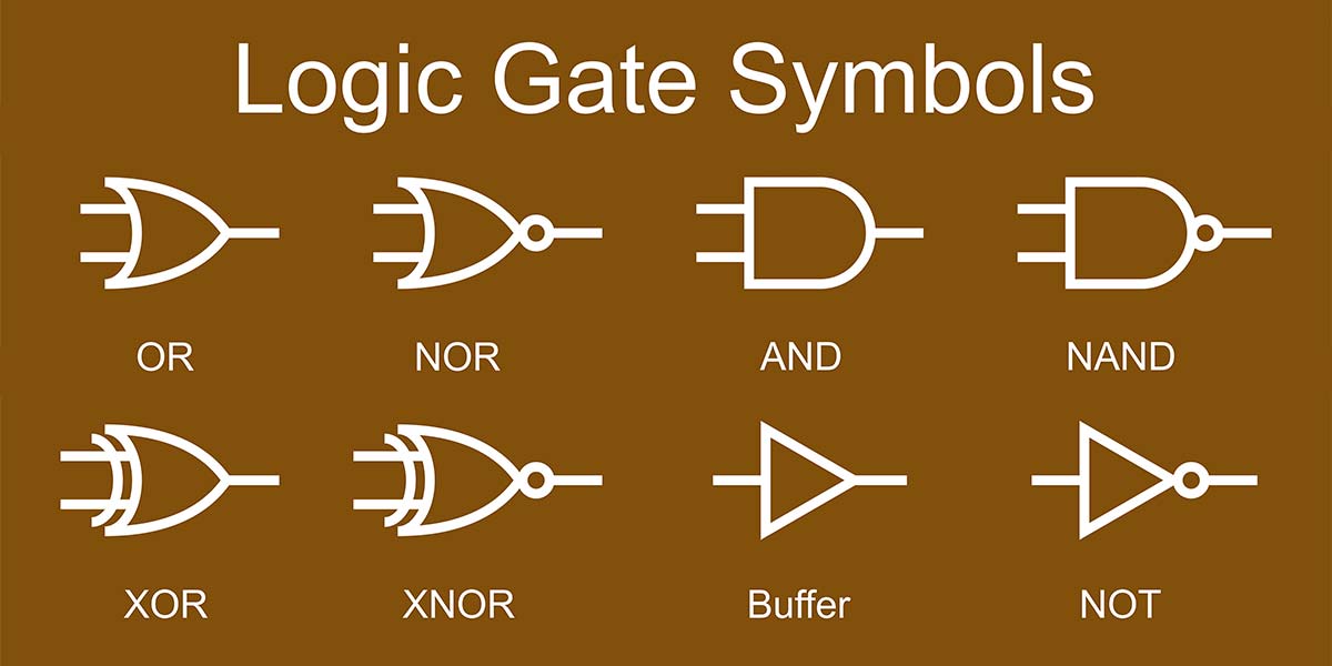
Logic Gates Symbol CAD Block And Typical Drawing For Designers
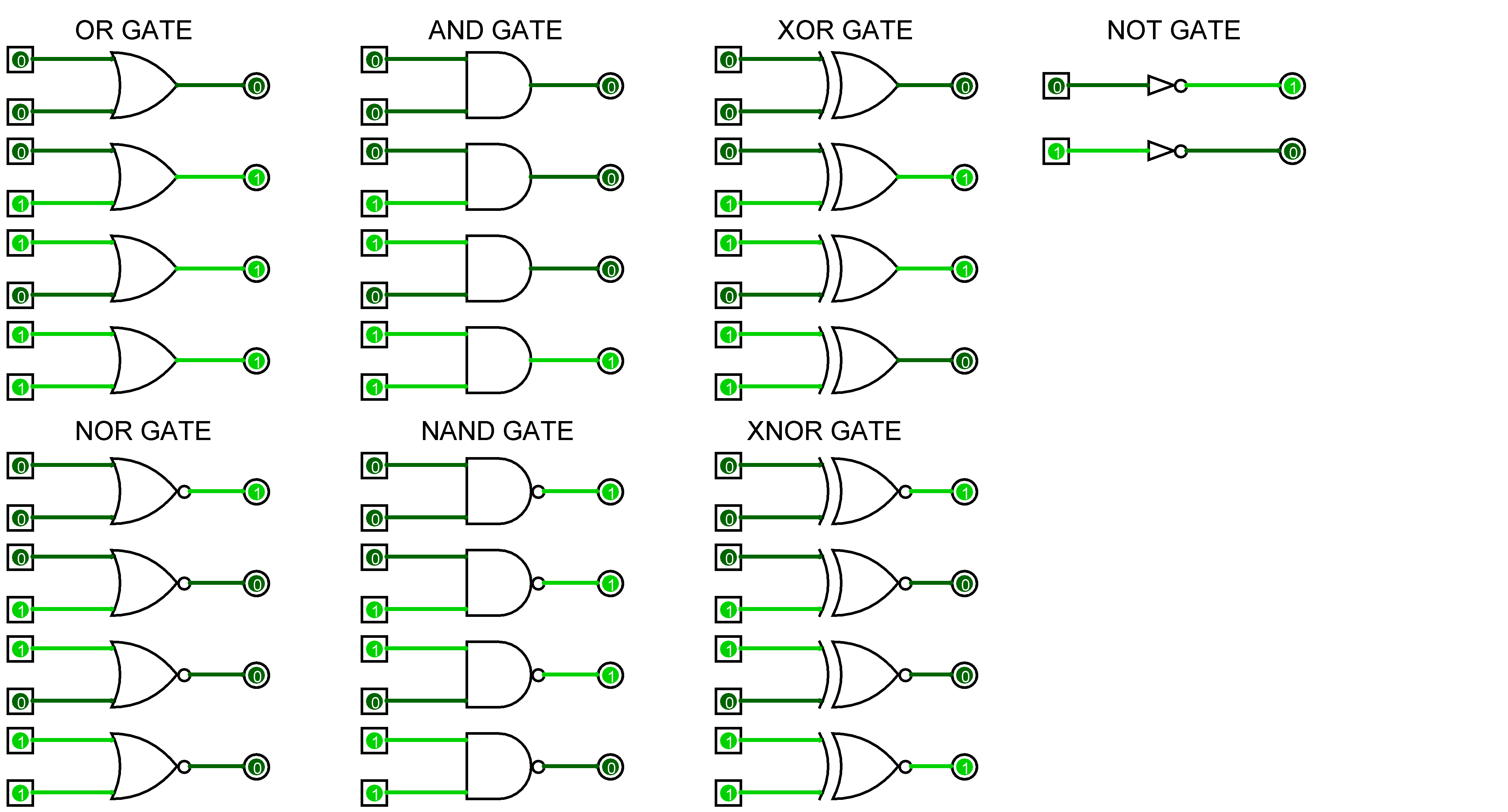
Logic Gates Animation Inst Tools

Logic Gates YouTube
![[Solved] How to draw logic gates in tikz 9to5Science](https://i.stack.imgur.com/ut5wE.png)
[Solved] How to draw logic gates in tikz 9to5Science
Circuit Diagram For Or Gate
Logic Gate Circuit Diagram Examples Wiring Diagram Schemas
Logic Gates Schematic Diagram
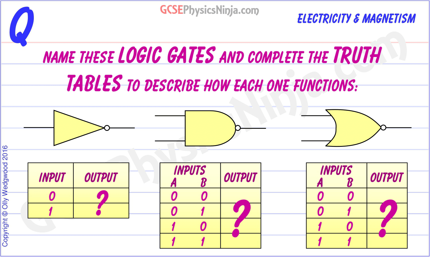
48. Logic gates and truth tables 2
Draw Logic Gates Online ClipArt Best
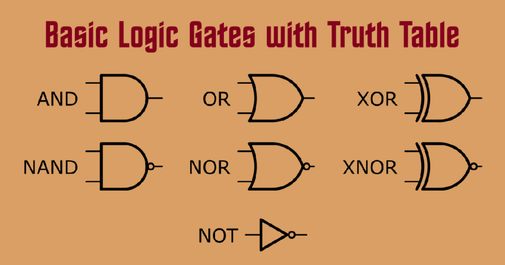
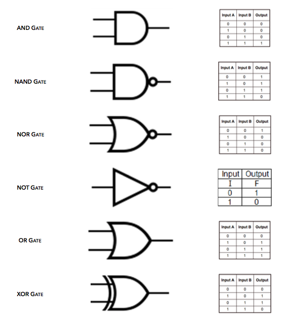
Basics of Logic Gates with Truth Table AHIRLABS
Web A Logic Gate Is A Device That Performs A Boolean Function, A Logical Operation Performed On One Or More Binary Inputs That Produces A Single Binary Output.
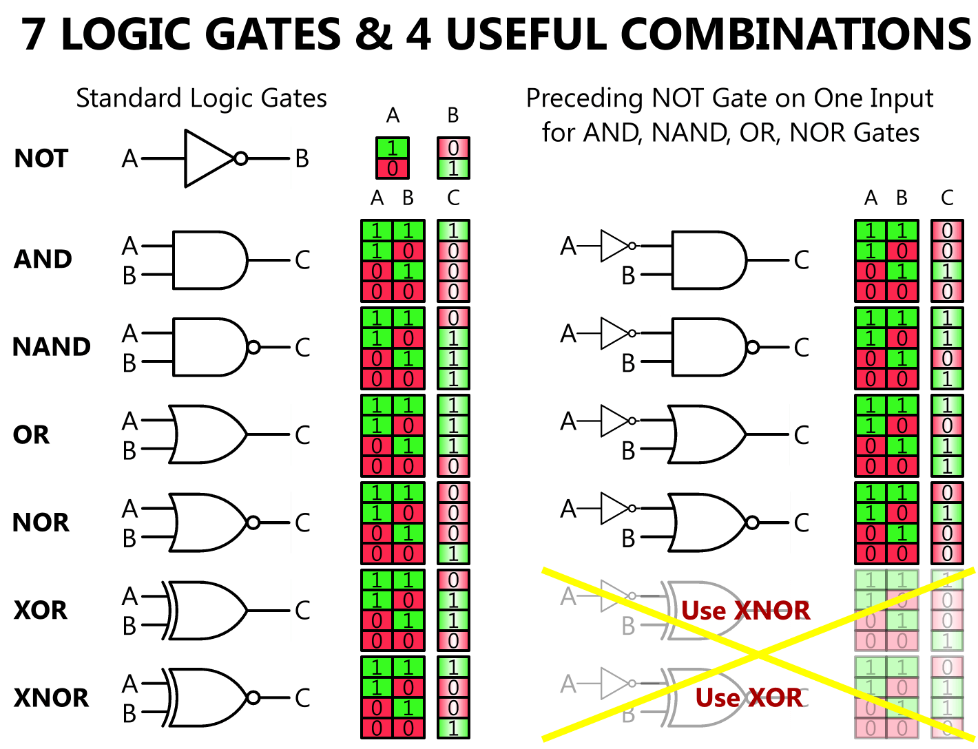
And, Or, Xor, Not, Nand, Nor And Xnor.
Web The Basic Logic Gates Are Classified Into Seven Types:
Therefore The Output From The Or Gate Becomes:
Related Post: