Drawing Moment Diagrams
Drawing Moment Diagrams - Web you’ll understand how to model beam elements that resist axial force, shear forces and bending moments within the direct stiffness method. If you’re not in the mood. Single point load this is example shows how to use the steps outlined in the steps tab to draw shear force and bending moment diagrams. We go through breaking a beam into segments, and then we learn about the relationships between shear force and. The arrows should be drawn to scale and must be oriented in the correct direction. The calculator is fully customisable to suit most beams,. Once the cg is located, the force vectors can be drawn around it. This can be done by using a balance or by calculation. Web learn to draw shear force and moment diagrams using 2 methods, step by step. For practical purposes, this diagram is often used in the same circumstances as the shear diagram, and generally both diagrams will be created for analysis in these. Knowing forces effect on beams. You’ll have your own analysis software that can generate shear force diagrams, bending moment diagrams, deflected shapes and more. Single point load this is example shows how to use the steps outlined in the steps tab to draw shear force and bending moment diagrams. Web moment diagrams are similar to shear diagrams, use them to. The #1 source for free engineering tutorials being able to draw shear force diagrams (sfd) and bending moment diagrams (bmd) is a critical skill for any student studying statics, mechanics of materials, or structural engineering. The arrows should be drawn to scale and must be oriented in the correct direction. Web the construction of bending moment (and shear force) diagrams. Web shear force and bending moment diagrams are powerful graphical methods that are used to analyze a beam under loading. The importance of sign convention, coordinate direction and behaviour at supports is given explicit attention in several examples. Web beamguru.com is a online calculator that generates bending moment diagrams (bmd) and shear force diagrams (sfd), axial force diagrams (afd) for. Web this is an example problem that will show you how to graphically draw a shear and moment diagram for a beam. Once the cg is located, the force vectors can be drawn around it. You’ll have your own analysis software that can generate shear force diagrams, bending moment diagrams, deflected shapes and more. If you’re not in the mood.. The #1 source for free engineering tutorials being able to draw shear force diagrams (sfd) and bending moment diagrams (bmd) is a critical skill for any student studying statics, mechanics of materials, or structural engineering. Web this is an example problem that will show you how to graphically draw a shear and moment diagram for a beam. Enter beam length. Distributed force this example deals with a constant distributed force (shear is. This is made easier because the curves are integrals or derivatives of one another, so graphical sketching can take advantage of relations among slopes and areas. Web 𝐌𝐲 𝐄𝐧𝐠𝐢𝐧𝐞𝐞𝐫𝐢𝐧𝐠 𝐍𝐨𝐭𝐞𝐛𝐨𝐨𝐤 for notes! Web learn to draw shear force and moment diagrams using 2 methods, step by step. For. The arrows should be drawn to scale and must be oriented in the correct direction. This page will walk you through what shear forces and bending moments are, why they are useful, the procedure for drawing the diagrams and some other keys aspects as well. Web in this video i explain how to draw shear and moment diagrams. The calculator. Web in this video i explain how to draw shear and moment diagrams. Web the moment diagram will plot out the internal bending moment within a horizontal beam that is subjected to multiple forces and moments perpendicular to the length of the beam. You’ll have your own analysis software that can generate shear force diagrams, bending moment diagrams, deflected shapes. Knowing forces effect on beams. Web beamguru.com is a online calculator that generates bending moment diagrams (bmd) and shear force diagrams (sfd), axial force diagrams (afd) for any statically determinate (most simply supported and cantilever beams) and statically indeterminate beams, frames and trusses. Web the moment diagram will plot out the internal bending moment within a horizontal beam that is. In general the process goes like this:1) calcul. Web determining shear forces and bending moments along the length of a beam typically involves three steps: Single point load this is example shows how to use the steps outlined in the steps tab to draw shear force and bending moment diagrams. Skyciv also has a free beam calculator for you to. Web bending moment (m) = (force) x (distance between the point of application of the force and the point at which you need to calculate the bending moment (bm)) bm @ a: Web in this video i explain how to draw shear and moment diagrams. The arrows should be drawn to scale and must be oriented in the correct direction. Web learn to draw shear force and moment diagrams using 2 methods, step by step. Web it is often possible to sketch \(v\) and \(m\) diagrams without actually drawing free body diagrams or writing equilibrium equations. Web 𝐌𝐲 𝐄𝐧𝐠𝐢𝐧𝐞𝐞𝐫𝐢𝐧𝐠 𝐍𝐨𝐭𝐞𝐛𝐨𝐨𝐤 for notes! We go through breaking a beam into segments, and then we learn about the relationships between shear force and. Web everything you need to know about shear and bending moment diagrams for beams, including point loads, distributed loads (triangular too), and external couple. In general the process goes like this:1) calcul. Single point load this is example shows how to use the steps outlined in the steps tab to draw shear force and bending moment diagrams. Web moment diagrams are similar to shear diagrams, use them to find the location and value of the maximum positive and negative moment, or the moment at any specific location. Web the first step in drawing a moment diagram is to determine the location of the center of gravity (cg) of the structure. Mc = bending moment due to the 20kn force + bending moment due to the 10kn\m udl If you’re not in the mood. The internal shear force refers to the force that resists the sliding or separation of beam layers along its length, while the bending moment. This page will walk you through what shear forces and bending moments are, why they are useful, the procedure for drawing the diagrams and some other keys aspects as well.
Learn How To Draw Shear Force And Bending Moment Diagrams Engineering

Mechanics Map Shear and Moment Diagrams

Moment Diagrams Constructed by the Method of Superposition
The Ultimate Guide to Shear and Moment Diagrams

How to draw shear and moment diagrams YouTube

Ultimate Guide to Shear Force and Bending Moment Diagrams
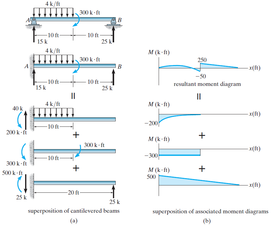
Moment Diagrams Constructed by the Method of Superposition
» How to Draw Moment Diagrams ReviewCivilPE

Learn How To Draw Shear Force And Bending Moment Diagrams Engineering

Brief Information About Shear Force And Bending Moment Diagrams
I Explain The Calculus Involved In Drawing Them And The Steps Are Written Out Below.check Out.
This Can Be Done By Using A Balance Or By Calculation.
Knowing Forces Effect On Beams.
Has Graph Paper, Study Tips, And Some Sudoku Puzzles Or Downtime Between Classes!
Related Post: