Drawing Symbols For Piping
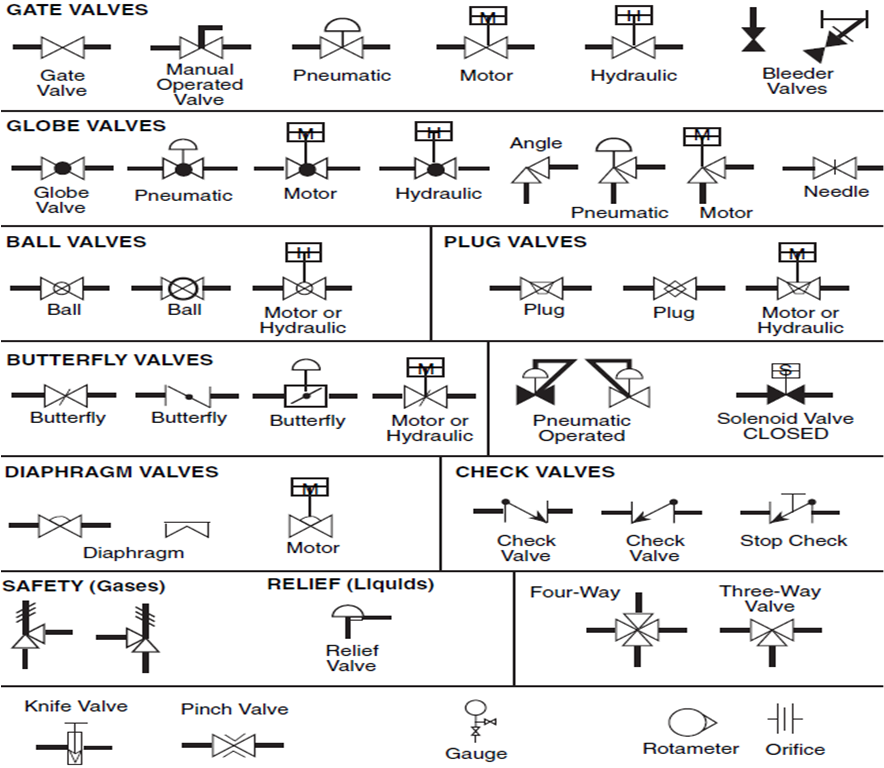
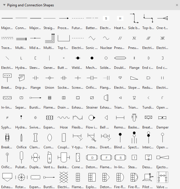
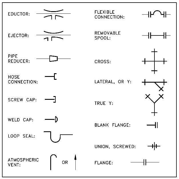
Drawing Symbols For Piping - Piping isometric symbols and conventions are employed to depict different components of pipeline systems, such as valves, fittings, and connections. 6 provides symbols for plumbing components. Symbols have been based generally on the philosophy described in the isa s5.1 standard. Isometric views can be identified by their characteristic lines and angles. These symbols are used to indicate the type of connection, the direction of flow, and the size of the pipe. These symbols can represent actuators, sensors, and controllers and may be apparent in most, if not all, system diagrams. Checkout list of such symbols given below. Web piping material specifications (pms). Edrawmax specializes in diagramming and visualizing. Detailed diagramming options for fast, precise drawing. The drawing axes of the isometrics intersect at an angle of 60°. Web use of piping symbols: Web piping and instrument diagram standard symbols detailed documentation provides a standard set of shapes & symbols for documenting p&id and pfd, including standard shapes of instrument, valves, pump, heating exchanges, mixers, crushers, vessels, compressors, filters, motors and connecting shapes. Web piping material. Web piping and instrument diagram standard symbols detailed documentation provides a standard set of shapes & symbols for documenting p&id and pfd, including standard shapes of instrument, valves, pump, heating exchanges, mixers, crushers, vessels, compressors, filters, motors and connecting shapes. Familiarize yourself with these symbols for better comprehension. 7 provides symbols for pipe and pipe fittings. Web isometric drawing symbols. Various symbols are used to indicate piping components, instrumentation, equipments in engineering drawings such as piping and instrumentation diagram (p&id), isometric drawings, plot plan, equipment layout, welding drawings etc. Learn from this article to know everything about plumbing symbols, and how to use or create plumbing symbols. Web piping and instrument diagram standard symbols detailed documentation provides a standard set. These drawings are developed from the schematics, basic design basis, and specifications for process piping. Web these symbols are categorized under the following headings: Web piping and instrument diagram standard symbols detailed documentation provides a standard set of shapes & symbols for documenting p&id and pfd, including standard shapes of instrument, valves, pump, heating exchanges, mixers, crushers, vessels, compressors, filters,. Pressure, temperature, flow, level, switches, alarms, and miscellaneous. And since lucidchart's symbols are based on the isa s5 standards, your p&ids will be welcome in any professional context. Web plot plan layout piping isometric drawing types of piping drawings for designing processes or power piping, mostly five types of piping drawings are developed. Web to mostly colored p&id symbols exist. Piping isometric symbols and conventions are employed to depict different components of pipeline systems, such as valves, fittings, and connections. Here’s where you find details about materials of construction, gaskets, bolts, fittings. Electrical gadgets (motors, generators, and turbines) heat exchangers; Some individuals will not see these in their line of work but it is important to be aware of them.. Web type of piping joint: Edrawmax specializes in diagramming and visualizing. Piping components (pipes, flanges, and fittings) valves; Symbols have been based generally on the philosophy described in the isa s5.1 standard. Some individuals will not see these in their line of work but it is important to be aware of them. Web piping and instrumentation diagrams (p&ids) use specific symbols to show the connectivity of equipment, sensors, and valves in a control system. Pipe drawings are much different from specific weld symbols but they do have a similar relationship from part to symbol. Web a complete collection of the most used p&id symbols for lines, piping, valves, instruments, pumps, compressors, pressure. Web piping symbols are important to read drawings as it gives quick reference about fittings, joint types, valve types and any other special component to be used. Detailed diagramming options for fast, precise drawing. Pressure, temperature, flow, level, switches, alarms, and miscellaneous. Familiarize yourself with these symbols for better comprehension. Electrical gadgets (motors, generators, and turbines) heat exchangers; Web piping symbols, also known as pipe drawings, are a set of symbols used in metal fabrication drawings to represent the various types of pipes and fittings used in industrial piping systems. The drawing axes of the isometrics intersect at an angle of 60°. Learn from this article to know everything about plumbing symbols, and how to use or create. Web piping and instrument diagram standard symbols detailed documentation provides a standard set of shapes & symbols for documenting p&id and pfd, including standard shapes of instrument, valves, pump, heating exchanges, mixers, crushers, vessels, compressors, filters, motors and connecting shapes. 6 provides symbols for plumbing components. Checkout list of such symbols given below. Familiarize yourself with these symbols for better comprehension. These symbols are categorized under the following headings: Web piping material specifications (pms). Edrawmax specializes in diagramming and visualizing. Symbols have been based generally on the philosophy described in the isa s5.1 standard. When the pipe doesn’t move in the exact north, south, east, or west direction then the movement is shown with help of rolling angles. Piping and pipeline drawing symbols throw lights on the type of joint like buttweld, socket weld, or threaded. Web a piping isometric drawing is a technical drawing that depicts a pipe spool or a complete pipeline using an isometric representation. These symbols are used to indicate the type of connection, the direction of flow, and the size of the pipe. 5 provides symbols for fans, pumps, and turbines. These symbols can represent actuators, sensors, and controllers and may be apparent in most, if not all, system diagrams. Pipe drawings are much different from specific weld symbols but they do have a similar relationship from part to symbol. Here’s where you find details about materials of construction, gaskets, bolts, fittings.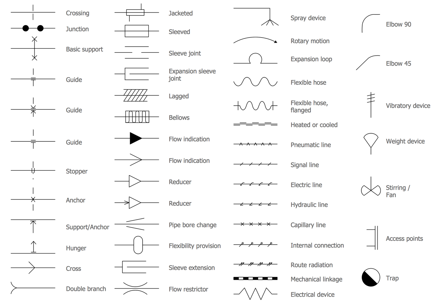
Piping and Instrumentation Diagram Software

Basic Piping Isometric Symbols Piping Analysis YouTube

What is Piping Isometric drawing? How to Read Piping Drawing? ALL
Piping Schematic Symbols Pdf
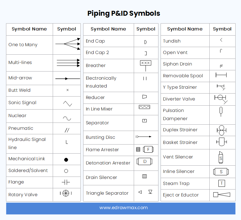
Plumbing and Piping Plan Symbols Edraw
Piping and Instrumentation Drawing (P&ID) Tutorials Part 3 (2023)

Piping Isometric Drawings The Piping Engineering World

Basic Diagrams & Symbols Piping Analysis Pumps Center
What is a P&ID Beginner’s Guide EdrawMax Online

Piping Isometric Drawing Symbols Pdf at Explore
Web Isometric Drawing Symbols For Piping Fittings.
Pressure, Temperature, Flow, Level, Switches, Alarms, And Miscellaneous.
Web To Mostly Colored P&Id Symbols Exist Scheduled Below:
*Also Used For General Stop Valve When Amplified By Specification.
Related Post: