Hidden Lines In Engineering Drawing
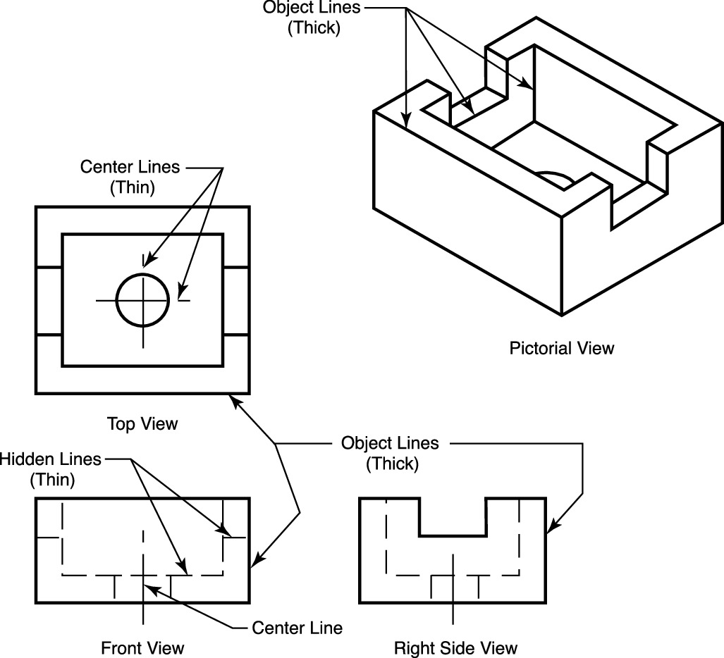
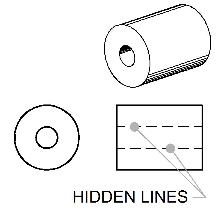
Hidden Lines In Engineering Drawing - Cutting plane lines are used in section drawings to. A hidden line should begin with a dash in contact with the line from which it starts, except when it is the continuation of an unbroken line. These lines are drawn to represent hidden or invisible edges of the objects. Figure 3.46 shows a case in which hidden lines are needed because a projecting part cannot be clearly shown without them. Web 18.06.2020 by andreas velling engineering drawing basics explained an engineering drawing is a subcategory of technical drawings. Nuts, screws, washers) are typically not sectioned. Section lines and symbols section lines, or hatching, that represent the cut surface usually consist of thin parallel lines, as shown below, drawn at an angle of approximately 45° to the principal edges or axes of the part. Web in my first semester of university, i had my intro to engineering drawing class. Web all hidden lines behind the cutting plane must not be shown, but all visible lines should be shown! They provide features that can not be seen in a. Web hidden lines (thin) type lines consist of thin short dashes, closely and evenly spaced. Web 18.06.2020 by andreas velling engineering drawing basics explained an engineering drawing is a subcategory of technical drawings. Engineering drawings use standardised language and symbols. Their purpose is to clearly and accurately depict the shape and size of the object, as well as to distinguish. Web in my first semester of university, i had my intro to engineering drawing class. Web hidden lines in cad. Nuts, screws, washers) are typically not sectioned. Web 1) always show all hidden lines unless it creates too much clutter. Web a hidden line, also known as a hidden object line is a medium weight line, made of short dashes. Web all hidden lines behind the cutting plane must not be shown, but all visible lines should be shown! Their purpose is to clearly and accurately depict the shape and size of the object, as well as to distinguish it from any. Engineering drawings use standardised language and symbols. Dimensions to hidden views are bad practise, and should be avoided.. They provide features that can not be seen in a. The dashed line is used to indicate hidden details like hidden outlines and hidden edges. Dimensions to hidden views are bad practise, and should be avoided. Web types of lines for technical drawings visible lines. Web 18.06.2020 by andreas velling engineering drawing basics explained an engineering drawing is a subcategory. Hidden lines are used to represent features or edges that are not visible from a particular viewpoint. Dimensions to hidden views are bad practise, and should be avoided. These lines are drawn to represent hidden or invisible edges of the objects. These features are typically inside the object or obscured by other surfaces. Web hidden lines (thin) type lines consist. Web hidden lines in a drawing represent the edges where surfaces meet but are not directly visible. A hidden line should begin with a dash in contact with the line from which it starts, except when it is the continuation of an unbroken line. They are drawn as short dashes that are equally spaced. The dashed line is used to. 2) never use hidden lines unless it helps to clarify the shape of the part (in other words, if the the part is defined with, say, 3 or more views/sections and those views are enough to clarify the shape of the part, no hidden lines are needed). Web hidden lines hidden edge lines are drawn with short dashes and are. They provide features that can not be seen in a. Web an engineering drawing is a type of technical drawing that is used to convey information about an object. Their purpose is to clearly and accurately depict the shape and size of the object, as well as to distinguish it from any. Often they are omitted in an isometric view.. Web all hidden lines behind the cutting plane must not be shown, but all visible lines should be shown! Section lines and symbols section lines, or hatching, that represent the cut surface usually consist of thin parallel lines, as shown below, drawn at an angle of approximately 45° to the principal edges or axes of the part. The dashed line. The dashed line may be either thick or thin, but only one type (thick or thin) should be used on a single drawing or set of drawings. Web types of lines for technical drawings visible lines. To show internal features with more clarity than regular projections or hidden lines,it also helps reducing number of hidden lines.in assembly drawings, hardware components. Hidden lines are omitted from pictorial drawings unless they are needed to make the drawing clear. These lines are drawn to represent hidden or invisible edges of the objects. They are an essential part of any technical drawing as a tool for. They provide features that can not be seen in a. To show internal features with more clarity than regular projections or hidden lines,it also helps reducing number of hidden lines.in assembly drawings, hardware components (e.g. Let's just say the professor was very good at engineering drawing but not. These features are typically inside the object or obscured by other surfaces. Web hidden lines in a drawing represent the edges where surfaces meet but are not directly visible. Web a broken out section is easy to do on a drafting board, and hard to do in 3d cad like solidworks. Sometimes they are used to make a drawing easier to understand. Web types of lines for technical drawings visible lines. Hidden lines are used to represent features or edges that are not visible from a particular viewpoint. You have learned that when making a multiview sketch, hidden edges and surfaces are usually shown with hidden (dash) lines. This animated video details and showcases their use, purpose and advantages & disadvantages to using them. Section lines and symbols section lines, or hatching, that represent the cut surface usually consist of thin parallel lines, as shown below, drawn at an angle of approximately 45° to the principal edges or axes of the part. Basically, this type of drawing aims at clearly capturing all the geometric features of products and.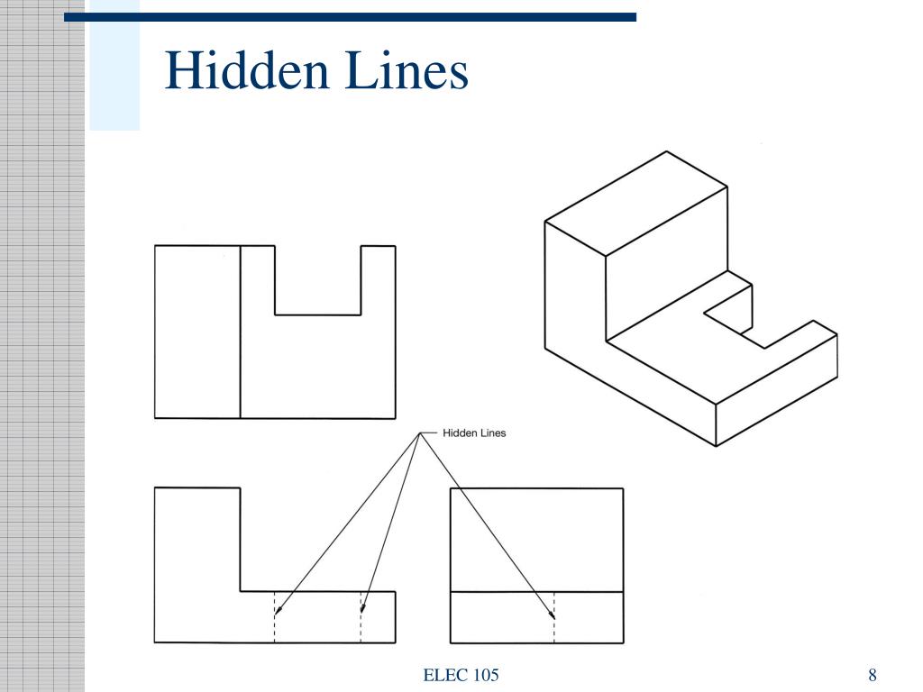
PPT Engineering Drawing PowerPoint Presentation, free download ID
Quick Reference For Using Technical Drawings Scroll Saw Woodworking
2020 Drawing Hidden Lines for an Orthographic drawing using alignment

Hidden Lines and Center Lines YouTube

Type of Line used in (ED) Engineering Drawing Phantom line hidden

Hidden Lines YouTube
Hidden Lines ToolNotes

ENGR 1304 Ch2 Views and Perspectives
PPT Engineering Drawing Lecture 5 PROJECTION THEORY PowerPoint

Do you use hidden lines in perspective and isometric drawings? r
Web An Engineering Drawing (Also Named As Mechanical Drawing, Manufacturing Blueprints, Drawings, Dimensional Prints, And More) Refers To One Of The Technical Drawings, Which Helps To Define Engineering Products’ Requirements.
Web Visible Lines Represent The Visible Edges, Boundaries, And Outlines Of Objects In Engineering Drawings.
The Dashed Line Is Used To Indicate Hidden Details Like Hidden Outlines And Hidden Edges.
Web Hidden Lines In Cad.
Related Post: