Hidden Lines In Engineering Drawings
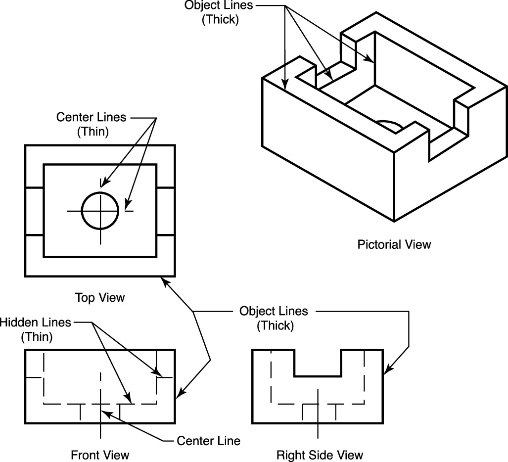
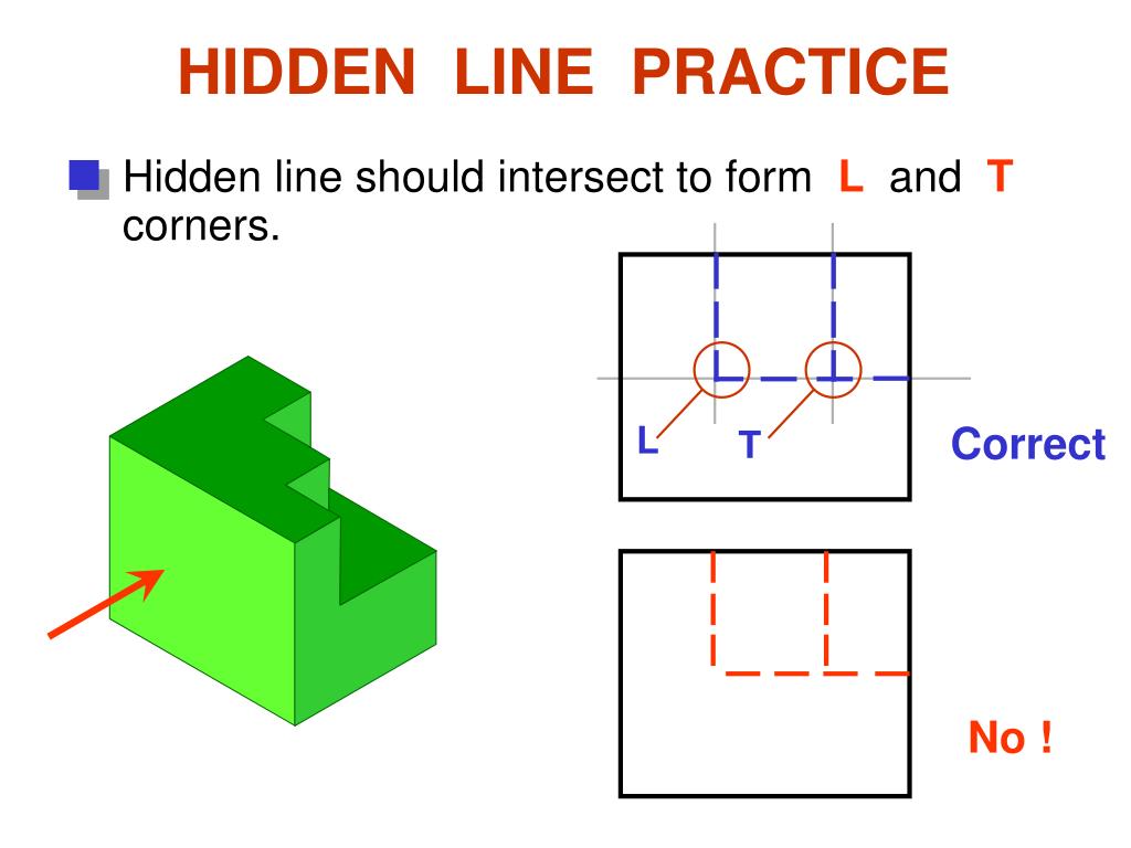
Hidden Lines In Engineering Drawings - These lines are drawn to represent hidden or invisible edges of the objects. Sometimes they are used to make a drawing easier to understand. Web engineering drawing abbreviations and symbols. Web published oct 15, 2023 + follow introduction to lines in engineering drawing lines in engineering drawing are more than just strokes on paper; As in all sectional drawings, the cutting plane take precedence over the center line. 2) never use hidden lines unless it helps to clarify the shape of the part (in other words, if the the part is defined with, say, 3 or more views/sections and those views are enough to clarify the shape of the part, no hidden lines are needed). Web in an engineering drawing, visible lines are the thick, solid lines that represent the visible edges and boundaries of an object or part. They are dark and thick lines of any engineering design drawing. Hidden edge lines are drawn with short dashes and are used to show hidden features of an object. Hidden lines are used to represent features or edges that are not visible from a particular viewpoint. Hidden lines will always begin and end with a dash. These features are typically inside the object or obscured by other surfaces. Hidden lines show edges and contours of important features that are obscured by the geometry of the part. The purpose is to convey all the information necessary for manufacturing a product or a part. Web engineering drawing abbreviations. Hidden lines are used to represent features or edges that are not visible from a particular viewpoint. Cutting plane lines are used in section drawings to. Hidden lines show edges and contours of important features that are obscured by the geometry of the part. Web the sectional view is applicable to objects like engine blocks, where the interior details are. Web visible lines are used to represent features that can be seen in the current view. It is standard practice to use dashes to represent any line of an object that is hidden from view. Web 1) always show all hidden lines unless it creates too much clutter. Hidden lines, as you already know, are used to represent features that. These lines are drawn to represent hidden or invisible edges of the objects. Web engineering drawing abbreviations and symbols. They are dark and thick lines of any engineering design drawing. My understanding is that should and shall are used deliberately in standards, with a precise grammatical meaning. They are an essential part of any technical drawing as a tool for. There was also a view expressed by me in a thread that hidden lines should never be shown in a drawing as a good practice though. Cutting plane lines are used in section drawings to. Hidden lines will always begin and end with a dash. Web visible lines represent the visible edges, boundaries, and outlines of objects in engineering drawings.. As in all sectional drawings, the cutting plane take precedence over the center line. Their purpose is to clearly and accurately depict the shape and size of the object, as well as to distinguish it from any. Here is another example of a half section. Sometimes the length of the dash will need to be adjusted to show a break,. A hidden line should begin with a dash in contact with the line from which it starts, except when it is the continuation of. The dashed line may be either thick or thin, but only one type (thick or thin) should be used on a single drawing or set of drawings. 2) never use hidden lines unless it helps to. There was also a view expressed by me in a thread that hidden lines should never be shown in a drawing as a good practice though. Web a hidden line, also known as a hidden object line is a medium weight line, made of short dashes about 1/8” long with 1/16”gaps, to show edges, surfaces and corners which cannot be. Web the dashed line is used to indicate hidden details like hidden outlines and hidden edges. Hidden lines will always begin and end with a dash. Sometimes the length of the dash will need to be adjusted to show a break, but the overall appearance of the dashes. Web hidden lines (thin) type lines consist of thin short dashes, closely. As in all sectional drawings, the cutting plane take precedence over the center line. My understanding is that should and shall are used deliberately in standards, with a precise grammatical meaning. Hidden lines, as you already know, are used to represent features that cannot be seen in the current view. They are drawn as short dashes that are equally spaced.. Web 18.06.2020 by andreas velling engineering drawing basics explained an engineering drawing is a subcategory of technical drawings. Here is another example of a half section. A hidden line should begin with a dash in contact with the line from which it starts, except when it is the continuation of. Web it is frequently used for symmetrical objects. My understanding is that should and shall are used deliberately in standards, with a precise grammatical meaning. Web visible lines are used to represent features that can be seen in the current view. They are dark and thick lines of any engineering design drawing. Hidden lines show edges and contours of important features that are obscured by the geometry of the part. Web engineering drawing abbreviations and symbols. Sometimes the length of the dash will need to be adjusted to show a break, but the overall appearance of the dashes. To read an ed, you must first become familiar with the various symbols, abbreviations, and diagram basics. They are drawn as short dashes that are equally spaced. Web #1 s srinivasaniyer1 new member this thread has been started to get your views as mechanical engineers and not as pro/e users.there was a thread by puppet on what you would like to see on a drawing? Web a broken out section is easy to do on a drafting board, and hard to do in 3d cad like solidworks. Web visible lines represent the visible edges, boundaries, and outlines of objects in engineering drawings. Web published oct 15, 2023 + follow introduction to lines in engineering drawing lines in engineering drawing are more than just strokes on paper;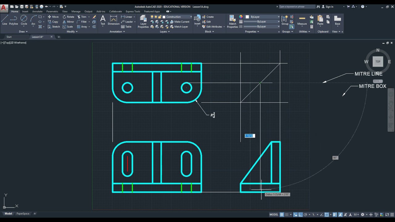
2020 Drawing Hidden Lines for an Orthographic drawing using alignment
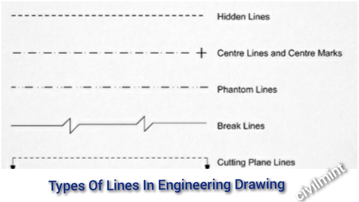
Types Of Lines In Engineering Drawing
Quick Reference For Using Technical Drawings Scroll Saw Woodworking

ENGR 1304 Ch2 Views and Perspectives
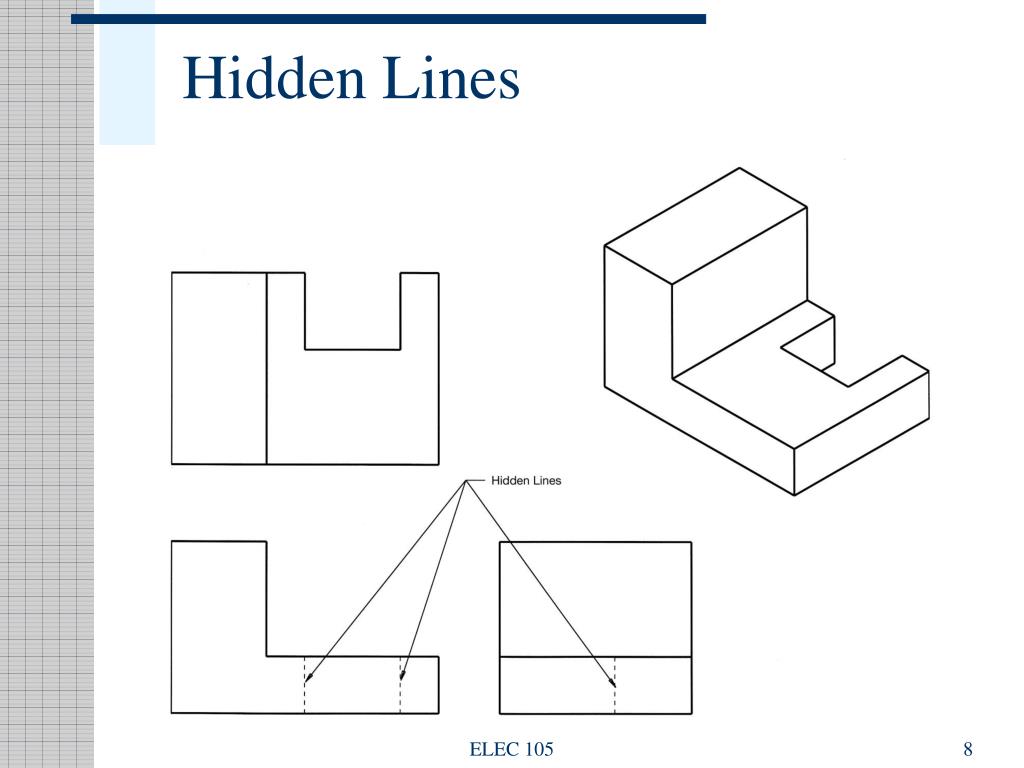
PPT Engineering Drawing PowerPoint Presentation, free download ID

Hidden Lines and Center Lines YouTube
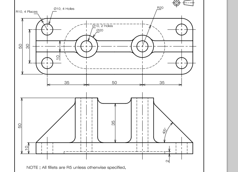
What are the hidden lines with radius 20 and depth 2 suppose to

Do you use hidden lines in perspective and isometric drawings? r

Type of Line used in (ED) Engineering Drawing Phantom line hidden
PPT Engineering Drawing Lecture 5 PROJECTION THEORY PowerPoint
Hidden Lines, As You Already Know, Are Used To Represent Features That Cannot Be Seen In The Current View.
Web For Mechanical Drawings Section Views Are Used To Reveal Interior Features Of An Object When Hidden Lines Cannot Properly Represent Them (E.g., With Multiple Interior Features And Excessive Overlaying Hidden Lines).
Web Hidden Lines In Cad.
Engineering Drawings Use Standardised Language And Symbols.
Related Post: