How To Draw Bode Plot From Transfer Function
How To Draw Bode Plot From Transfer Function - Several examples of the construction of bode plots are included here; Web to draw bode diagram there are four steps: Web how to draw bode plots given transfer function (part 1) raiya academy. + 1) 1 this is a stable real pole. Click on the transfer function in the table below to. Since the transfer function will always result in a real voltage, the following features can appear: In terms of circuits this means we might have a v in v i n and a v out v o u t where our transfer function is h (s) = v out v in h ( s) = v o u t v i n Rewrite the transfer function in proper form. For both plots, the horizontal axis is either frequency (f) or angular frequency (ω), measured in hz and rad/s, respectively. Bode plots using transfer function. Web example 1 obtain the bode plot of the system given by the transfer function ( s ). Web how to draw bode plots given transfer function (part 1) raiya academy. Bode plots of transfer functions give the frequency response of a control system to compute the points for a bode plot: Web matlab (with the sketched bode plot superimposed. Rewrite the transfer function in proper form. For both plots, the horizontal axis is either frequency (f) or angular frequency (ω), measured in hz and rad/s, respectively. Separate the transfer function into its constituent parts. Bode plots using transfer function. The magnitude is plotted in decibels (db) and the phase is plotted in degrees. Rewrite the transfer function in proper form. Web bode plots consist of two individual graphs: A) a semilog plot of gain vs frequency b) a semilog plot of phase shift vs frequency. Web a video that very clearly explains along with an example: Bode plots of transfer functions give the frequency response of a control system to compute the points. Frequency is the logarithmic axis on both plots. Web how to draw bode plots given transfer function (part 1) raiya academy. So for ω = 2 ω << , i.e., for small values of ω ( j ) 1. Web making the bode plots for a transfer function involve drawing both the magnitude and phase plots. Bode plots of transfer. Make both the lowest order term in the numerator and denominator unity. Web to draw bode diagram there are four steps: Inspection of t(s) in normalized form to: Each of these can appear in multiple orders (two poles at the same frequency, for example) additional features of the function are the constant g0, and the. Bode plots of transfer functions. Web to draw bode diagram there are four steps: The magnitude is plotted in decibels (db) while the phase is plotted in degrees ( ). Since the transfer function will always result in a real voltage, the following features can appear: Compute input interpretation input value bode plot show stability margins nyquist plot show nyquist grid show stability margins nichols. Web creating bode plots from a transfer function given the transfer function: From the open loop response bode plots various design changes may be explored. Several examples of the construction of bode plots are included here; The first thing we’ll need is called transfer function. Bode plots using transfer function. The magnitude is plotted in decibels (db) while the phase is plotted in degrees ( ). %transfer function converted to db phasehrad=atan(w/1). We will workout step by step how to convert the transfer function into a standard form and how to generate. We will use the asymptotic. Web the first part of making a bode plot is finding the magnitude. + 1) 1 this is a stable real pole. For both plots, the horizontal axis is either frequency (f) or angular frequency (ω), measured in hz and rad/s respectively. Determine the zeros and poles of the function: Web the keystone will be the bode plots of each part of the system that comprise the open loop response. Rewrite the transfer. Web to draw bode diagram there are four steps: Web a video that very clearly explains along with an example: Web math input extended keyboard examples random computational inputs: Bode plots using transfer function. H ( j ω ) = v out vin (1) Rewrite the transfer function in proper form. Web how to draw bode plots given transfer function (part 1) raiya academy. Web making the bode plots for a transfer function involve drawing both the magnitude and phase plots. Separate the transfer function into its constituent parts. = 2 s 1 we convert the transfer function in the following format by substituting s j = ω ( j ). A system’s transfer function is given. Bode plots using transfer function. Usually denoted as h (s) h ( s) or h (jω) h ( j ω). Determine the zeros and poles of the function: Web example 1 obtain the bode plot of the system given by the transfer function ( s ). The magnitude is plotted in decibels (db) and the phase is plotted in degrees. Compute input interpretation input value bode plot show stability margins nyquist plot show nyquist grid show stability margins nichols plot show nichols grid show stability margins Inspection of t(s) in normalized form to: Generally a transfer function is equivalent to the ratio of an output to an input. How do you plot a bode plot for a given transfer function.if you want to see how to derive a transfer function from a bode. So for ω = 2 ω << , i.e., for small values of ω ( j ) 1.
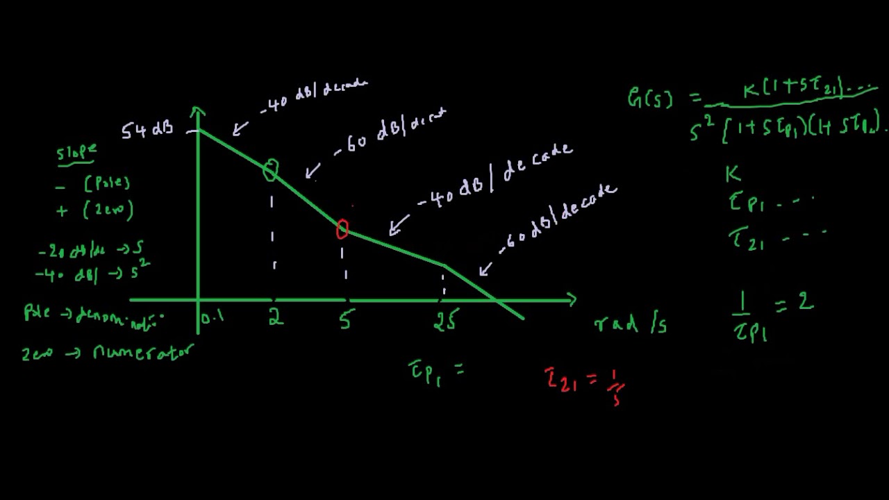
Drawing Bode Plot From Transfer Function SecondOrder Double Zero

ME 340 Example Drawing Bode Plot of a Transfer Function 2 YouTube

Drawing Bode Plot From Transfer Function ThirdOrder System Real

Bode Plot EXAMPLE YouTube

Deriving the Transfer Function from Bode Plot Example 1 YouTube

How to Derive a Transfer Function Given a Bode Plot (Part 3) YouTube
Bode Plot Example Bode Diagram Example MATLAB Electrical Academia
How to find transfer function from Bode Plot YouTube
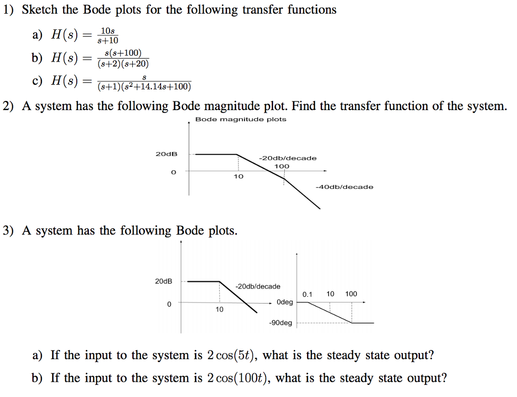
Solved Sketch The Bode Plots For The Following Transfer F...
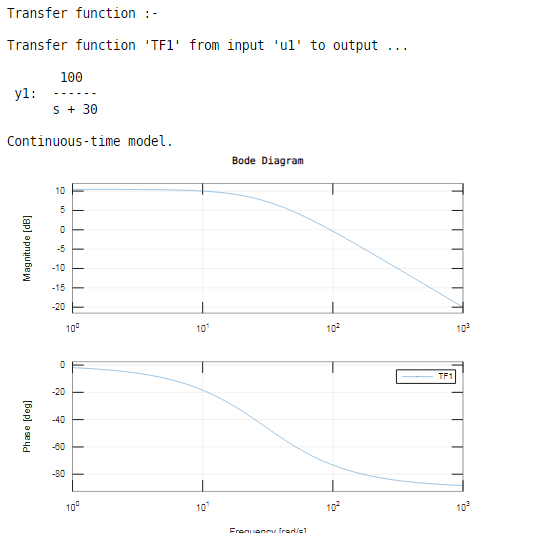
Bode Plot Matlab How to do Bode Plot Matlab with examples?
Web In This Video, We Will Discuss How To Draw The Bode Plot From A Given Transfer Function.
H ( J Ω ) = V Out Vin (1)
Web This Video Illustrates How To Draw Bode Plot For Transfer Function Having A Quadratic Factor (Second Order Factor).
For Both Plots, The Horizontal Axis Is Either Frequency (F) Or Angular Frequency (Ω), Measured In Hz And Rad/S Respectively.
Related Post: