How To Draw Phasor Diagram
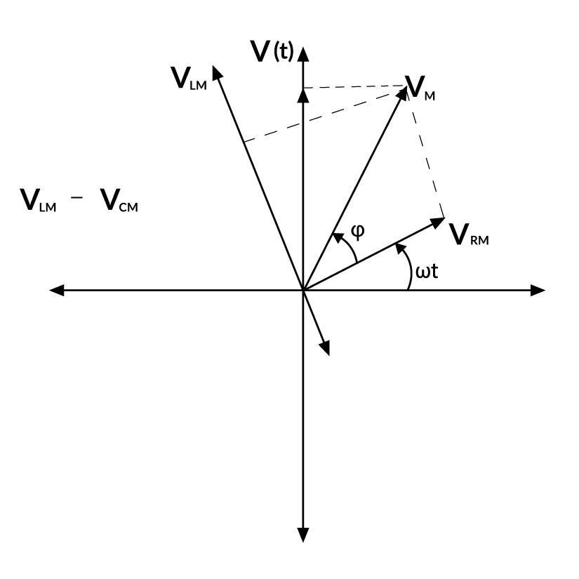
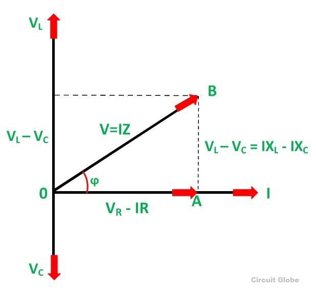
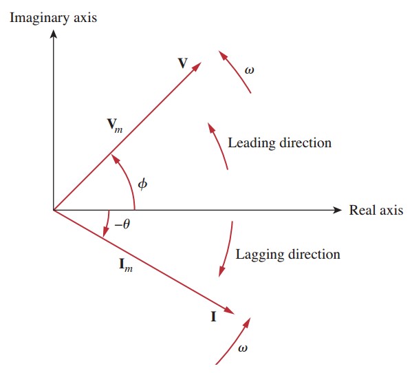
How To Draw Phasor Diagram - Web phasor diagrams are a representation of an oscillating quantity as a vector rotating in phase space with an angular velocity equal to the angular frequency of the original trigonometric function. Web this is simply a guide to help you draw a phasor diagram to scale. Web phasor diagrams are very convenient when we need to add and subtract two signals that are not in phase. Addition of instantaneous values since kirchhoff’s voltage law applies to the circuit in figure 1 at every instant, \ [\begin {matrix}e= { {v}_ {t}}= { {v}_ {r}}+ { {v}_ {l}} & {} & \left ( 1 \right) \\\end {matrix}\] Web how to create a phasor diagram online: No more ratta maar 209k subscribers subscribe 24k views 2 years ago electrical interview question | basic electrical in. Web phasor diagrams can be used to represent two or more stationary sinusoidal quantities at any instant in time. They are also a useful tool to add/subtract oscillations. Draw the current phasor horizontally to the right as the reference phasor. Web phasor diagram for series rlc circuits. Phasor diagrams can be drawn to represent more than two sinusoids. Web this video provides a very easy concept of drawing phasor diagram for any complex network. They can be either voltage, current or some other alternating quantity but the frequency of all of them must be the same. Web phasor diagrams can be used to represent two or more. The projection of the phasor onto an axis at a specific time gives the value of the quantity at that time. Addition of instantaneous values since kirchhoff’s voltage law applies to the circuit in figure 1 at every instant, \ [\begin {matrix}e= { {v}_ {t}}= { {v}_ {r}}+ { {v}_ {l}} & {} & \left ( 1 \right) \\\end {matrix}\]. Web phasor diagrams present a graphical representation, plotted on a coordinate system, of the phase relationship between the voltages and currents within passive components or a whole circuit. The projection of the phasor onto an axis at a specific time gives the value of the quantity at that time. Web in order to distinguish between different alternating quantities like current,. Web phasor diagrams present a graphical representation, plotted on a coordinate system, of the phase relationship between the voltages and currents within passive components or a whole circuit. Phasor diagrams can be drawn to represent more than two sinusoids. If you observe the above waveform, the voltage waveform(v = v m sin ωt) starts at time zero on the horizontal. Phasor diagrams can be drawn to represent more than two sinusoids. Web in order to distinguish between different alternating quantities like current, voltage or flux, different types of arrow heads may be used. Draw the resultant and determine the total. The other phasors are drawn either by lagging or leading with respect to the reference axis. Since the current flowing. You must have a good knowledge of how a capacitor works to appreciate this. Web how to draw a phasor diagram of any circuit is discussed here step by step.subscribe my new channel here : This demonstration shows a phasor diagram in an ac series rlc circuit. Web in order to distinguish between different alternating quantities like current, voltage or. Web phasors are rotating vectors having the length equal to the peak value of oscillations, and the angular speed equal to the angular frequency of the oscillations. The current in an rlc series circuit is determined by the differential equation. The magnitude and phase of each wave can then be drawn as a vector, and the relationships between the waves. Web the phasor diagram is based on the complex plane discussed previously where the horizontal is the real axis and the vertical is the imaginary (\(j\)) axis. Web phasors are rotating vectors having the length equal to the peak value of oscillations, and the angular speed equal to the angular frequency of the oscillations. The other phasors are drawn either. The current in an rlc series circuit is determined by the differential equation. Image used courtesy of adobe stock The current phasors may be drawn with closed arrow heads while the voltage phasors with open arrow heads. Draw the current phasor horizontally to the right as the reference phasor. Web phasor diagram | how to draw a phasor diagram for. Addition of instantaneous values since kirchhoff’s voltage law applies to the circuit in figure 1 at every instant, \ [\begin {matrix}e= { {v}_ {t}}= { {v}_ {r}}+ { {v}_ {l}} & {} & \left ( 1 \right) \\\end {matrix}\] It also shows how to calculate the power factor and the phase angle. V 1 (t)+v 2 (t)=(v 1 +v 2. When two signals are in phase, let’s say v 1 (t)=v 1 sin(ωt) and v 2 (t)=v 2 sin(ωt) it is indeed easy to addition them : Oh, and if you do not appreciate this, quit now. If you observe the above waveform, the voltage waveform(v = v m sin ωt) starts at time zero on the horizontal axis. It also shows how to calculate the power factor and the phase angle. Image used courtesy of adobe stock No more ratta maar 209k subscribers subscribe 24k views 2 years ago electrical interview question | basic electrical in. Web while drawing the phasor diagram, one phasor is designated as a reference phasor. Draw the resultant and determine the total. Phasor diagrams can be drawn to represent more than two sinusoids. Web calculations with phasors require a specialized form of algebra, which is described later in the chapter. Web how to draw a phasor diagram of any circuit is discussed here step by step.subscribe my new channel here : Web this is simply a guide to help you draw a phasor diagram to scale. They are helpful in depicting the phase relationships between two or more oscillations. Web phasor diagrams are a representation of an oscillating quantity as a vector rotating in phase space with an angular velocity equal to the angular frequency of the original trigonometric function. Addition of instantaneous values since kirchhoff’s voltage law applies to the circuit in figure 1 at every instant, \ [\begin {matrix}e= { {v}_ {t}}= { {v}_ {r}}+ { {v}_ {l}} & {} & \left ( 1 \right) \\\end {matrix}\] This demonstration shows a phasor diagram in an ac series rlc circuit.
How to draw a Phasor diagram

How to draw a Phasor Diagram ? Step by Step Tech TALKS YouTube
How To Draw A Phasor Diagram Free Wiring Diagram
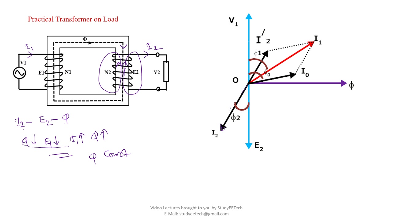
How to Draw Transformer Phasor Diagram YouTube
Introduction to Phasors Definition, Examples, Diagrams, and FAQs
Phasor Diagram Rlc Circuit

how to draw phasor diagram for any circuit star connection start

How to draw phasor diagram from polar form phasors ? YouTube
What is Phasor and Phasor Diagram Simple Explanation Wira Electrical

How to draw phasor diagram of transformer on load in easy way YouTube
And At The End, Voltage And Current Relationship Between The Basic Circuit Elements Like Resistor, Inductor, And.
Web The Phasor Diagram Is Based On The Complex Plane Discussed Previously Where The Horizontal Is The Real Axis And The Vertical Is The Imaginary (\(J\)) Axis.
Web Phasors Are Rotating Vectors Having The Length Equal To The Peak Value Of Oscillations, And The Angular Speed Equal To The Angular Frequency Of The Oscillations.
Since The Current Flowing Through The Circuit Is Common To All Three Circuit Elements We Can Use This As The Reference Vector With The Three Voltage Vectors Drawn Relative To This At Their.
Related Post: