Isometric Drawing North South East West
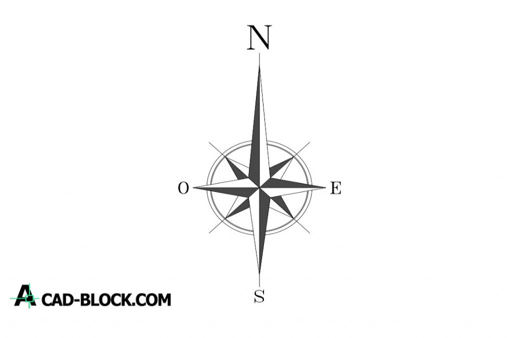
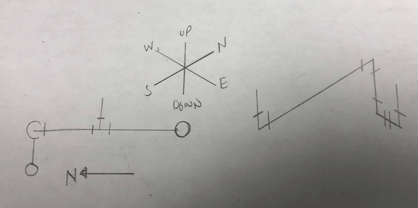
Isometric Drawing North South East West - Web information on the arrangement drawing aids in the development of the piping model and isometric drawings. This is a plan drawing. Figures 10.48 through 10.51 represent the north, south, east, and west elevations, respectively. This can also represent a line which not traveling in the exact north, south, east, west, up, or down direction. Web a rule is, that the angle between true north and plant north can not exceed 45°. Web the isometric drawing’s line diagram is unable to specify line size. These four elevations are rendered views from a 3d model of. The iso, as isometric is commonly referred, is oriented on the grid relative to the north arrow found on plan drawings. Web if its labeled as an east elevation, then it is looking at the facility from the east direction. Web what is the north elevation in the drawing below? Web knowing that the piping arrangement drawing is a plan, or top, view drawing, a pipe can be determined to be turning north, south, east, or west when oriented relative to the drawing’s north arrow. Web agi32 has four preset isometric views available: These four elevations are rendered views from a 3d model of. Web this indicates the north, south,. Web find & download free graphic resources for north south east west symbol. However, a cluttered drawing with an unusual amount of notes does not promote clarity. Free for commercial use high quality images Web information on the arrangement drawing aids in the development of the piping model and isometric drawings. Showing what the north elevation actually is. Web plot plan layout drawing, and ; 294k views 7 years ago reading isometric drawing. Piping plan drawings/general arrangement drawings (gad) the piping plan or general arrangement drawings (fig. At 50°, for example, the plant north would be on the right side, so on the eastern side of the image. Actual line size can be obtained from bom or nb. Piping isometrics are generally produced from orthographic drawings and are important pieces of information to engineers. These four elevations are rendered views from a 3d model of. This will help you identify the other features on the drawing as they all relate to this directional orientation. Showing what the north elevation actually is. X = east west distance from new. Web isometrics are usually drawn from information found on a plan and sectional elevation views. The applied angles rotate the drawing to the selected viewing direction. 99,000+ vectors, stock photos & psd files. Web the isometric drawing’s line diagram is unable to specify line size. As an isometric for a particular line is developed, constant reference to the piping arrangement,. Guess which is the north elevation? Web the line diagram shown in the isometric drawing can’t define line size. Web if its labeled as an east elevation, then it is looking at the facility from the east direction. Divide the width and depth measurements equally. This is a plan drawing. This can also refer to a line that is not precisely moving in the directions of north, south, east, west, up, or down. At 50°, for example, the plant north would be on the right side, so on the eastern side of the image. Web about press copyright contact us creators advertise press copyright contact us creators advertise The iso,. Web plot plan layout drawing, and ; This can also refer to a line that is not precisely moving in the directions of north, south, east, west, up, or down. Web if its labeled as an east elevation, then it is looking at the facility from the east direction. Home qa / qc iso metric drawings interpretation. Figures 10.48 through. This can also refer to a line that is not precisely moving in the directions of north, south, east, west, up, or down. Drawing symbols, callouts, coordinates, and elevations provide detailed information of the pipe's configuration and routing through the unit. At 50°, for example, the plant north would be on the right side, so on the eastern side of. This can also represent a line which not traveling in the exact north, south, east, west, up, or down direction. 99,000+ vectors, stock photos & psd files. Free for commercial use high quality images Web knowing that the piping arrangement drawing is a plan, or top, view drawing, a pipe can be determined to be turning north, south, east, or. Once the orientation of the drawing is established, locate the directional indicators, which are typically labeled on the drawing as n, s, e, and w. Web last updated on sat, 03 jun 2023 | piping systems. These four elevations are rendered views from a 3d model of. Drawing symbols, callouts, coordinates, and elevations provide detailed information of the pipe's configuration and routing through the unit. As an isometric for a particular line is developed, constant reference to the piping arrangement, section, or elevation drawings is essential. Piping isometrics are generally produced from orthographic drawings and are important pieces of information to engineers. Web information on the arrangement drawing aids in the development of the piping model and isometric drawings. Piping plan drawings/general arrangement drawings (gad) the piping plan or general arrangement drawings (fig. Guess which is the north elevation? Home qa / qc iso metric drawings interpretation. This can also refer to a line that is not precisely moving in the directions of north, south, east, west, up, or down. What are east, west and south elevations? For example, a north arrow would be shown as an arrow pointing up with the abbreviation “n” beside it. Web a rule is, that the angle between true north and plant north can not exceed 45°. 2 = south west angle of new plant. This will help you identify the other features on the drawing as they all relate to this directional orientation.
CAD North CAD Blocks DWG Drawing Free Autocad Free CAD Blocks

️3d Isometric Drawing Worksheets Free Download Gambr.co

Isometrics Jeopardy Template

How to read piping isometric drawing pdf naasunrise

Isometric Drawing Lausanne Mathematics Teachers Network

isometric Google Search Isometric Drawing Examples, Isometric Sketch
North direction in model vs Isometrics Autodesk Community
Piping Isometrics demystified through practical examples

3D Compass North, South, East, West 4 Directions Stock Illustration
Isometric Grid Help Teaching Resources
However, A Cluttered Drawing With An Unusual Amount Of Notes Does Not Promote Clarity.
The Iso, As Isometric Is Commonly Referred, Is Oriented On The Grid Relative To The North Arrow Found On Plan Drawings.
99,000+ Vectors, Stock Photos & Psd Files.
Free For Commercial Use High Quality Images
Related Post:


