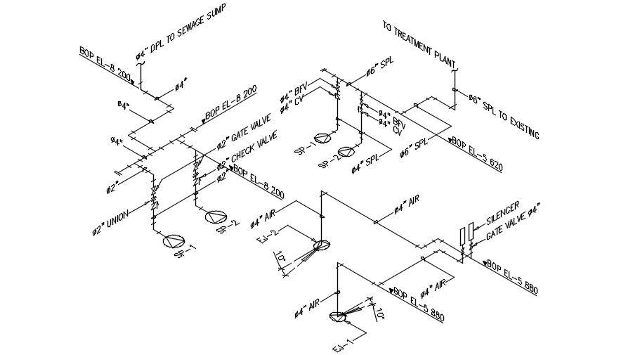
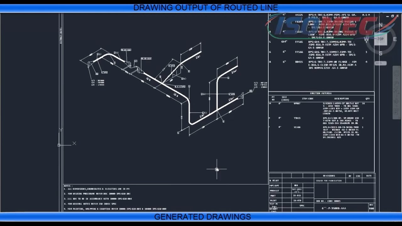
Isometric Drawing Pipeline
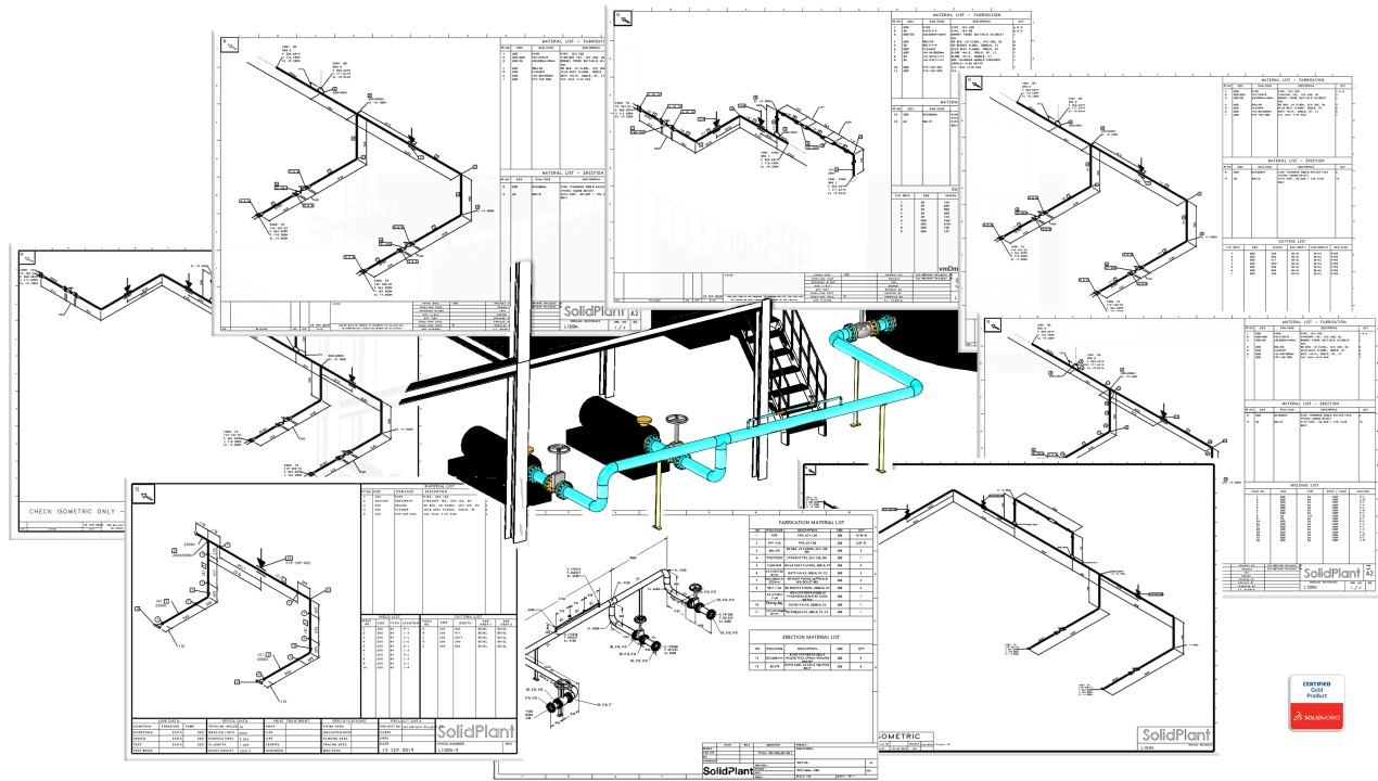
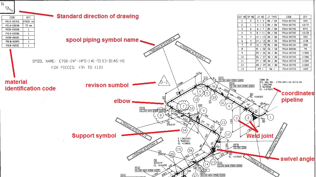
Isometric Drawing Pipeline - The drawing also includes annotations and dimensions, such as the distance between components and the angle of bends. Web piping isometric drawing is one of the most important deliverables of the piping discipline as it provides complete information of the piping routeto be erected at the construction site. Web pipeline isometrics are detailed drawings used in engineering and design to represent the 3d layout of a pipeline system on a 2d surface. So engineers and designers must be aware of the isometric preparation steps. Piping isometrics are typically drawn in single lines irrespective of the pipe’s size, with each pipe line drawn on a separate sheet. Engineers and technicians rely on these symbols to identify and understand the role of valves within the larger context of the piping infrastructure. Web what is piping isometric drawing? Π x diameter of the. Web piping isometric drawing types of piping drawings for designing processes or power piping, mostly five types of piping drawings are developed. The main body of an isometric piping drawing consists of the following: Engineers and technicians rely on these symbols to identify and understand the role of valves within the larger context of the piping infrastructure. Web piping isometric drawing is an isometric representation of single pipe line in a plant. Web piping isometric drawing study. Isometric drawings are commonly used in industries such as the oil and gas industry, petrochemical industry, and. Calculations for piping data from isometric drawing. Web in pipeline isometric drawings, valves are depicted using iso standard symbols that convey their type, function, and operation. The symbols that represent fittings, valves and flanges are modified to adapt to the isometric grid. The main body of a piping isometric drawing is consist of:. Web piping isometric drawing is one of. Engineers and technicians rely on these symbols to identify and understand the role of valves within the larger context of the piping infrastructure. Web these common components are as follows: So engineers and designers must be aware of the isometric preparation steps. Web features of piping isometric drawing it is not drawn to the scale, but it is proportionate with. Web a piping isometric drawing includes information about the type of pipe, the diameter and thickness of the pipe, the location of valves, fittings, and other components, and the direction of flow. Web an isometric drawing is a type of pictorial drawing in which three sides of an object can be seen in one view. Web isometric drawings are, by. In this article, a few of the salient points are discussed. Π x diameter of the. Web pipeline isometrics are detailed drawings used in engineering and design to represent the 3d layout of a pipeline system on a 2d surface. Orthographic and isometric north arrows. We are concluding our first pipefitter series run with a video on how to draw. The drawing also includes annotations and dimensions, such as the distance between components and the angle of bends. Web what is piping isometric drawing? Orthographic and isometric north arrows. Isometric drawings are commonly used in industries such as the oil and gas industry, petrochemical industry, and plumbing for planning, design, construction, and pipeline maintenance. Web features of piping isometric drawing. Web the isometrics drawing are created from information found on a plan and elevation views. Line number flow direction piping components Web an isometric drawing is a type of pictorial drawing in which three sides of an object can be seen in one view. In this article, a few of the salient points are discussed. These drawings are developed from. It’s popular within the process piping industry because it can be laid out and drawn with ease and portrays the object in a. Isometric drawing area isometric drawing name and location of the pipeline equipment coordinates for all. Web what is piping isometric drawing? When using software, it is. Knowing that the piping arrangement drawing is a plan, or top,. Web in pipeline isometric drawings, valves are depicted using iso standard symbols that convey their type, function, and operation. Isometrics are usually drawn from information found on a plan and elevation views. Web isometric drawings are, by definition, a visual depiction of a 3d routed line in a 2d plane that combines pipe height and length in a single drawing. Web pipeline isometrics are detailed drawings used in engineering and design to represent the 3d layout of a pipeline system on a 2d surface. Web piping isometric drawing types of piping drawings for designing processes or power piping, mostly five types of piping drawings are developed. Reading a piping isometric drawing basic training. Line number flow direction piping components In. Title block the title block should have the following data to ensure thorough communication of the pipeline. Web create the piping isometric drawing manually 1. Calculations for piping data from isometric drawing. Web 42k views 1 year ago tutorials for pipe fitters and fabricators. With the help of sophisticated computer aided design (cad) tools, piping engineers and designers can produce isometric drawings from 3d models with ease. Reading a piping isometric drawing basic training. Piping isometric drawing consists of three sections. Automated bill of materials no more tedious material tracking when creating a pipe isometric drawing. Symbols like fittings, valves and flanges are modified to adapt to the isometric grid. Pipes are shown in the same size. How to read iso drawings. We are concluding our first pipefitter series run with a video on how to draw isometric drawings. Engineers and technicians rely on these symbols to identify and understand the role of valves within the larger context of the piping infrastructure. Create a drawing sheet for isometrics. Web the isometrics drawing are created from information found on a plan and elevation views. These various types of piping drawings in engineering organizations are:Isometric view of the main steam pipeline. Download Scientific Diagram
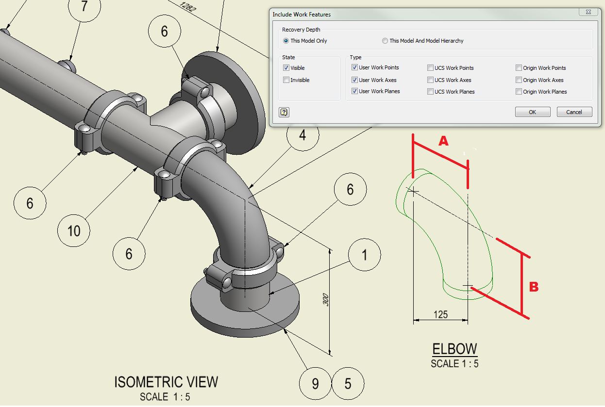
How to create piping isometric drawings with SOLIDWORKS
Isometric Pipe Drawing at GetDrawings Free download

How to read isometric drawing piping dadver
Learn isometric drawings (piping isometric)

How to read piping isometric drawing, Pipe fitter training, Watch the
Piping isometric drawing examples planninglio
Piping Isometric Drawings Autodesk Community
Piping Isometric Drawing at Explore collection of

Piping Design Basics Piping Isometric Drawings Piping Isometrics
Isometric Drawing Area Isometric Drawing Name And Location Of The Pipeline Equipment Coordinates For All.
It’s Popular Within The Process Piping Industry Because It Can Be Laid Out And Drawn With Ease And Portrays The Object In A.
Draw The Route Of The Pipeline.
Web An Isometric Drawing Is A Type Of Pictorial Drawing In Which Three Sides Of An Object Can Be Seen In One View.
Related Post: