Isometric Drawing Piping Symbols
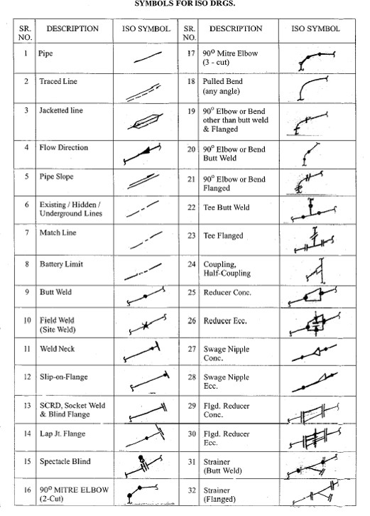
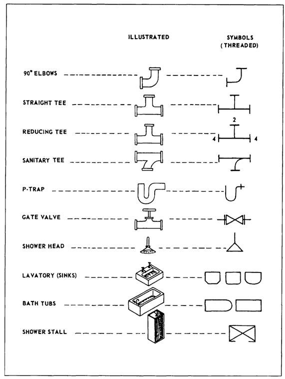
Isometric Drawing Piping Symbols - Web this is an isometric pipe drawing that explains how to identify the fittings. There is an end cap at the beginning of the line, from here the line is starting total 1 end cap is installed Checkout list of such symbols given below. So engineers and designers must be aware of the isometric preparation steps. Automatically set the grid and snap with a click of the mouse. Web the process of drafting isometric drawings for a pipeline system involves referencing the arrangements of the pipelines, sections, and elevation drawings during its development. Web isometric drawing symbols for valves buttweld ball valve buttweld butterfly valve buttweld check valve buttweld gate valve buttweld globe valve buttweld needle valve buttweld plug valve buttweld three way valve buttweld y type valve flanged ball valve flanged bottom valve flanged butterfly valve flanged check valve flanged diaphragm. Web isometric symbols for fittings, flanges, and valves represent all sizes of pipe. The use of coordinate and elevation callouts to determine configuration dimensions of the routed pipe is explained. Web piping symbols serve as the alphabet of isometric drawings, with each symbol representing a specific component, similar to words in a language. Automatically set the grid and snap with a click of the mouse. Accurate drawing symbols, callouts, precise coordinates, and elevations provide intricate information to the fabricator. Sometimes it is used in lieu of plans and elevations but typically it is used to supplement the plan drawings isometrics are used as fabrication & shop drawings for pipe run fabrication isometrics also. Web this is an isometric pipe drawing that explains how to identify the fittings. What is piping isometric drawing? The drawing axes of the isometrics intersect at an angle of 60°. In isometric drawings, pipes are represented as lines. In this article, a few of the salient points are discussed. All symbols are drawn to work with a grid system. Web isometric symbols for fittings, flanges, and valves represent all sizes of pipe. Lighter lines show connected pipe, and are not parts of the symbols. Sometimes it is used in lieu of plans and elevations but typically it is used to supplement the plan drawings isometrics are used as fabrication. As an isometric for a particular line is developed, constant reference to the piping arrangement, section, or elevation drawings is essential. Web symbols are shown in black lines. Web piping symbols are a quick reference to know about the type of fitting and component to be used. The use of coordinate and elevation callouts to determine configuration dimensions of the. Web piping symbols are a quick reference to know about the type of fitting and component to be used. Web symbols are shown in black lines. The drawing axes of the isometrics intersect at an angle of 60°. Although piping isometrics are not drawn to scale, it should be drawn proportionally. Web contains 845 isometric piping symbols in.dwg format. Drawing symbols, callouts, coordinates, and elevations provide detailed information of the pipe's configuration and routing through the unit. There is an end cap at the beginning of the line, from here the line is starting total 1 end cap is installed Fittings, flanges, and valves play essential roles in pipeline isometric drawings, each with unique symbols according to iso standards.. Web how to read piping isometric drawing symbols. Automatically set the grid and snap with a click of the mouse. Web the symbols that represent fittings, valves and flanges are modified to adapt to the isometric grid. Web piping isometric drawing is a 2d drawing that represents the 3d piping system in pictorial form for helping in fabrication and construction.. Web isometric drawing symbols for piping fittings. In this article, a few of the salient points are discussed. Accurate drawing symbols, callouts, precise coordinates, and elevations provide intricate information to the fabricator. This information is conveyed through the use of callouts and notes placed on the drawing. Web object in a realistic view. Accurate drawing symbols, callouts, precise coordinates, and elevations provide intricate information to the fabricator. Web piping symbols serve as the alphabet of isometric drawings, with each symbol representing a specific component, similar to words in a language. Various symbols are used to indicate piping components, instrumentation, equipments in engineering drawings such as piping and instrumentation diagram (p&id), isometric drawings, plot. What is piping isometric drawing? In this article, a few of the salient points are discussed. Web piping symbols are a quick reference to know about the type of fitting and component to be used. Although piping isometrics are not drawn to scale, it should be drawn proportionally. The use of coordinate and elevation callouts to determine configuration dimensions of. What is an isometric drawing? Web the symbols that represent fittings, valves and flanges are modified to adapt to the isometric grid. What is piping isometric drawing? Various symbols are used to indicate piping components, instrumentation, equipments in engineering drawings such as piping and instrumentation diagram (p&id), isometric drawings, plot plan, equipment layout, welding drawings etc. Web object in a realistic view. Web the fitting, flange, and valve drawing symbols unique to isometrics are depicted. Accurate drawing symbols, callouts, precise coordinates, and elevations provide intricate information to the fabricator. Web symbols are shown in black lines. Web piping symbols are a quick reference to know about the type of fitting and component to be used. Web how to read piping isometric drawing symbols. Usually, piping isometrics are drawn on preprinted paper, with lines of equilateral triangles form of 60°. Web piping symbols serve as the alphabet of isometric drawings, with each symbol representing a specific component, similar to words in a language. Checkout list of such symbols given below. Lighter lines show connected pipe, and are not parts of the symbols. Web piping isometric drawing is a 2d drawing that represents the 3d piping system in pictorial form for helping in fabrication and construction. Sometimes it is used in lieu of plans and elevations but typically it is used to supplement the plan drawings isometrics are used as fabrication & shop drawings for pipe run fabrication isometrics also provide a drafter with the ability to calculate angular offsets in the pipe run.
Basic Piping Isometric Symbols Piping Analysis YouTube
Isometric Piping Symbols

What is Piping Isometric drawing? How to Read Piping Drawing? ALL

Piping Isometric Drawing Symbols Pdf at Explore

How to read isometric drawing piping dadver

PIPE FITTING ISOMETRIC Free CAD Block Symbols And CAD Drawing

Piping Isometric Drawings The Piping Engineering World

Piping Coordination System Mechanical symbols for Isometric drawings

TP3 TP4 Itpa Piping Systems Beyond Discovery

Piping Isometric Drawing Symbols Pdf at Explore
There Is An End Cap At The Beginning Of The Line, From Here The Line Is Starting Total 1 End Cap Is Installed
The Drawing Axes Of The Isometrics Intersect At An Angle Of 60°.
Fittings, Flanges, And Valves Play Essential Roles In Pipeline Isometric Drawings, Each With Unique Symbols According To Iso Standards.
The Visualization, Representation, And Dimensioning Of Single, Multiangle, And Rolling Offsets Are Explained.
Related Post:
