List Of Engineering Drawing Symbols
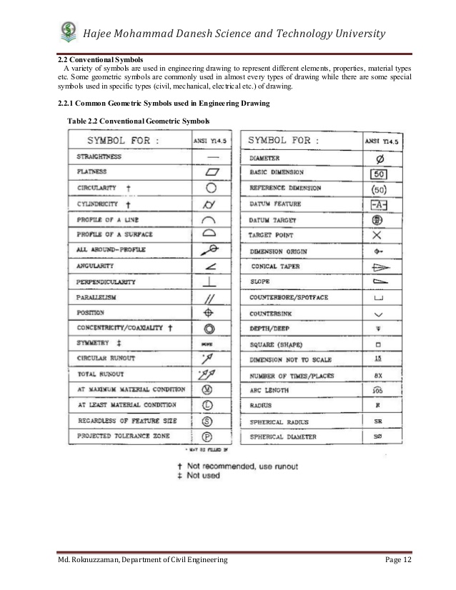
List Of Engineering Drawing Symbols - Web a convenient guide for geometric dimensioning and tolerancing (gd&t) symbols at your fingertips. Web engineering drawings use standardised language and symbols. Nuts are used in conjunction with bolts and. Web engineering drawing abbreviations and symbols are used to communicate and detail the characteristics of an engineering drawing. The symbols and abbreviations covered in this module relate to a few trades and professions. Also check gd & t symbols and terms here. Web gd&t drawings and symbols geometric tolerances are specified using symbols on a drawing. Technical drawings in general iso standards handbook: Here are some common engineering drawing abbreviations used in technical drawings: Bolts and screws are commonly used to hold components together. The basic symbol types used in engineering drawings are diameter, depth, radius, counterbore, spotface, and countersink. It describes typical applications and minimum content requirements. Web a booklet, symbols and abbreviations for use in electrical and electronic engineering courses, was published by the institution of electrical engineers in 1968 and 1971. The symbols covered in on the following pages are an. Web basic types of symbols used in engineering drawings are countersink, counterbore, spotface, depth, radius, and diameter. Web the following is a list of symbols that are commonly found in engineering drawings: It describes typical applications and minimum content requirements. The following are commonly used engineering drawing symbols and design elements. The basic symbol types used in engineering drawings are. Web 1.6 identify the symbols used on engineering p&ids to denote the location, either local or board mounted, of instruments, indicators, and controllers. Web engineering drawing abbreviations and symbols are used to communicate and detail the. Web gd&t drawings and symbols geometric tolerances are specified using symbols on a drawing. Basic types of symbols used in engineering drawings are countersink,. Bolts and screws are commonly used to hold components together. Surface texture symbols (y14.36) editions: Need to know for dispelling uncertainty in drawings. You can use this guide as a reference to help you decipher what is written on your engineering drawing. Web there are numerous abbreviations and symbols in various engineering drawing categories. View more 181 process flow diagram (pfd) symbols for engineers This list includes abbreviations common to the vocabulary of people who work with engineering drawings in the manufacture and inspection of parts and assemblies. Basic types of symbols used in engineering drawings are countersink, counterbore, spotface, depth, radius, and diameter. Web as in many technical fields, a wide array of. This list includes abbreviations common to the vocabulary of people who work with engineering drawings in the manufacture and inspection of parts and assemblies. Web the technical engineering drawing abbreviations we outline here are the terms used in the manufacturing (include precision cnc machining and more) and inspection of parts and assemblies. Web the following is a list of symbols. 1.7 identify the symbols used on engineering p&ids for the following types of instrument signal controllers and modifiers: Need to know for dispelling uncertainty in drawings. Technical drawings in general iso standards handbook: Web what are some examples of symbols used to represent different types of mechanical components? You can also check out the gd&t symbols and terms on our. The basic symbol types used in engineering drawings are diameter, depth, radius, counterbore, spotface, and countersink. To take account of the many revisions and additions to british and international standards 1.7 identify the symbols used on engineering p&ids for the following types of instrument signal controllers and modifiers: Web engineering drawing abbreviations and symbols are used to communicate and detail. The basic symbol types used in engineering drawings are diameter, depth, radius, counterbore, spotface, and countersink. View more 181 process flow diagram (pfd) symbols for engineers Web as in many technical fields, a wide array of abbreviations and symbols have been developed in engineering drawing during the 20th and 21st centuries. Need to know for dispelling uncertainty in drawings. You. Radius can be for the inside and outside curved surface on the part. Bolts and screws are commonly used to hold components together. This list includes abbreviations common to the vocabulary of people who work with engineering drawings in the manufacture and inspection of parts and assemblies. Currently, we have 16 symbols for geometric tolerances, which are categorized according to. The symbols covered in on the following pages are an example of the widespread use of symbols and abbreviations in industry. Click on the links below to learn more about each gd&t symbol or concept, and be sure to download the free wall chart for a quick reference when at your desk or on the shop floor. So let’s look at the different line and view types you will come across in the engineering discipline. 1.7 identify the symbols used on engineering p&ids for the following types of instrument signal controllers and modifiers: Also check gd & t symbols and terms here. Web as in many technical fields, a wide array of abbreviations and symbols have been developed in engineering drawing during the 20th and 21st centuries. Web engineering drawings use standardised language and symbols. Web engineering drawing abbreviations and symbols are used to communicate and detail the characteristics of an engineering drawing. Web basic and common symbols. The symbol for a bolt or screw typically consists of a straight line. Web a convenient guide for geometric dimensioning and tolerancing (gd&t) symbols at your fingertips. Here are more commonly used engineering drawing symbols and design elements as below. Below, you’ll find our list of drafting symbols in alphabetical order. Here are more commonly used engineering drawing symbols and design elements as below. Web the iso standards for technical drawings are found in a two volumes handbook: Web 1.6 identify the symbols used on engineering p&ids to denote the location, either local or board mounted, of instruments, indicators, and controllers.
Engineering Drawing Symbols And Their Meanings Pdf at PaintingValley

Engineering Drawing Symbols And Their Meanings Pdf at GetDrawings
Engineering Drawing Symbols And Their Meanings Pdf at PaintingValley

Engineering Drawing Symbols And Their Meanings Pdf at PaintingValley

Mechanical Engineering Drawing Symbols Pdf Free Download at

Engineering Drawing Symbols And Their Meanings Pdf at PaintingValley

ANSI Standard JSTD710 Architectural Drawing Symbols Bedrock Learning

Types of Engineering Drawing Symbols and Uses इंजीनियरिंग ड्राइंग के
Mechanical Engineering Symbols Cadbull

Civil Engineering Drawing Symbols And Their Meanings at PaintingValley
It Describes Typical Applications And Minimum Content Requirements.
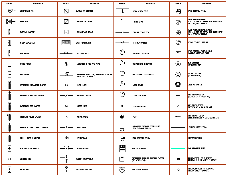
Web 363 Common P&Id Symbols:
They Are Also Used To Show The Fillets Given To Strengthen The Edges.
This Makes Understanding The Drawings Simple With Little To No Personal Interpretation Possibilities.
Related Post: