Multi Views Drawing
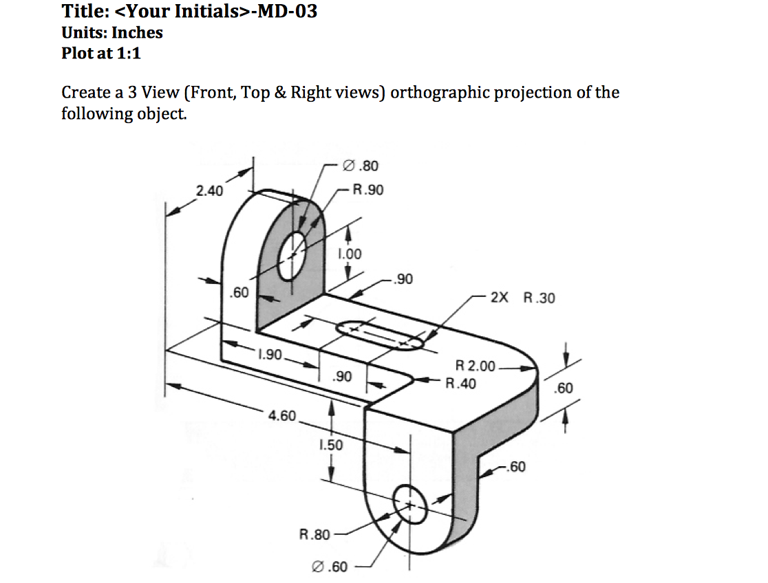
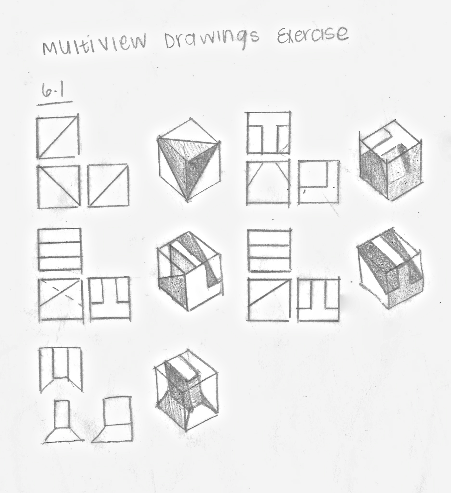
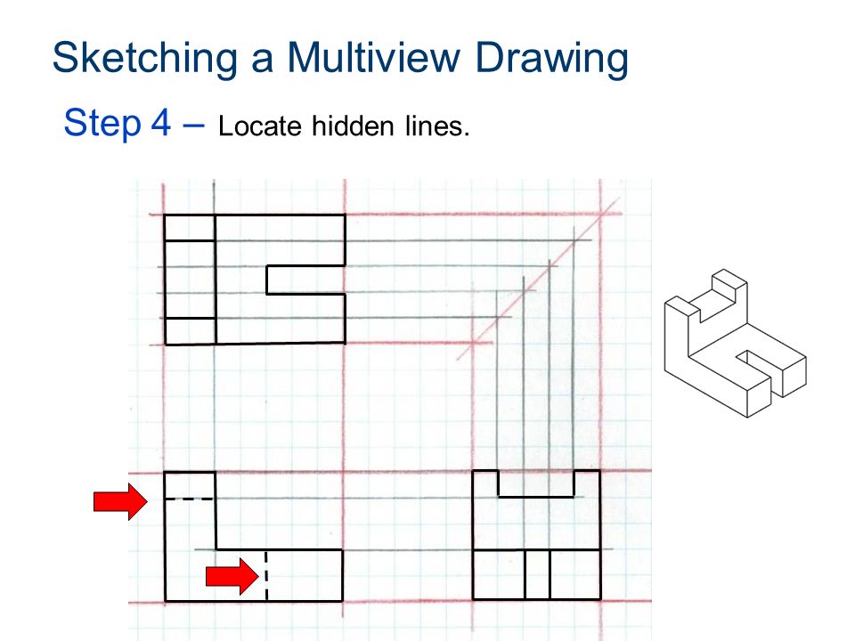
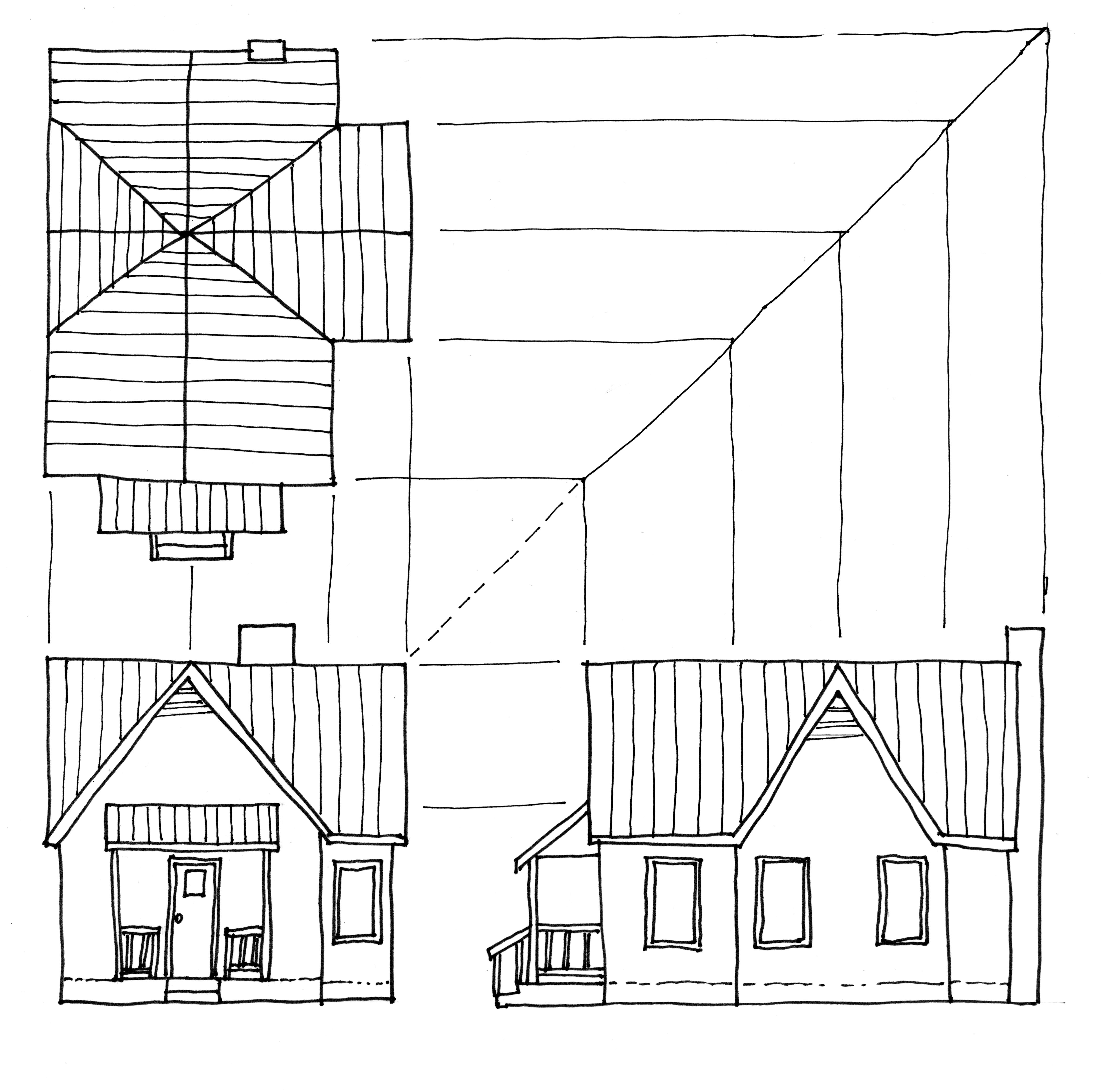
Multi Views Drawing - When you have completed this module, you will be able to: Monge defined a reference system of. A toy car shown from different orientations. The views are defined according to the positions of the 1 basic types of projection orthographic projection is a parallel type of projection technique in which the view directions are parallel but perpendicular to the image planes. In almost all objects, three views are adequate to describe it. The general recommendation are that thick lines are twice as thick as thin lines. The first step to create. Explain orthographic and multiview projection. Web multiview drawing the glass box principle. Web lines on an engineering drawing signify more than just the geometry of the object and it is important that the appropriate line type is used. 27k views 10 years ago basic drafting lectures. In multiview drawings, generally three views of an object are drawn, and the features and dimensions in each view accurately represent those of the object. 1. Line thickness for most engineering drawings you will require two thickness', a thick and thin line. Generally three views of an object are drawn, and the features and dimensions in each view accurately represent those of the object. Identify frontal, horizontal, and profile planes. In multiview drawings, generally three views of an object are drawn, and the features and dimensions. Engineering and technical graphics are dependent on projection methods. Web multiview drawings employ multiview projection techniques. The two projection methods primarily used in engineering graphics are: Among these, the engineering drawing or multiview drawing is a major means of communicating the design concept. An example of a multiview. Imagine a cube, 6 equal sides unfolded in the pattern you see in pic 1. 27k views 10 years ago basic drafting lectures. Engineering and technical graphics are dependent on projection methods. 1 basic types of projection orthographic projection is a parallel type of projection technique in which the view directions are parallel but perpendicular to the image planes. Identify. By doing this, it is easier to form a mental image from the multiview drawing. The first step to create. Line thickness for most engineering drawings you will require two thickness', a thick and thin line. Top, bottom, front, back, r side, and l side. Additionally, the spatial vis software has digitized multiview assignments with automatic grading and instantaneous feedback. Imagine a cube, 6 equal sides unfolded in the pattern you see in pic 1. Orthographic views (orthoviews for short) make it possible to describe a. A toy car shown from different orientations. The first step to create. In multiview drawings, generally three views of an object are drawn, and the features and dimensions in each view accurately represent those. To carry this principal further, place a plane on each side of the object for a total of six. Construct 3d models in autocad using multiview drawings. Web multiviews quadrants in descriptive geometry. An example of a multiview. Web types of views used in drawings. When you’re trying to draw a part, you draw each view as it’s seen from the position in the cube in 2d. This video goes over how to. A toy car shown from different orientations. Top, bottom, front, back, r side, and l side. Web lines on an engineering drawing signify more than just the geometry of the object and. Web multiviews quadrants in descriptive geometry. Orthographic projection is a technique that is used to create multiview drawings. Web lines on an engineering drawing signify more than just the geometry of the object and it is important that the appropriate line type is used. Gaspard monge's four quadrants and two planes. Imagine a cube, 6 equal sides unfolded in the. Understanding the views you have a total of 6 views you can put in a standard drawing*; Monge defined a reference system of. The views are defined according to the positions of the This video goes over how to. Generally three views of an object are drawn, and the features and dimensions in each view accurately represent those of the. It is called a multiview drawing. In multiview drawings, generally three views of an object are drawn, and the features and dimensions in each view accurately represent those of the object. Imagine a cube, 6 equal sides unfolded in the pattern you see in pic 1. It is called a multiview drawing. The first step to create. An example of a multiview. Identify frontal, horizontal, and profile planes. All projection theory is based on two. There are three types of pictorial views: This video goes over how to. Additionally, the spatial vis software has digitized multiview assignments with automatic grading and instantaneous feedback. Draw isometric drawings on an isometric grid using multiview drawings as a reference. A toy car shown from different orientations. The views are defined according to the positions of the The two projection methods primarily used in engineering graphics are: Orthographic projection is a technique that is used to create multiview drawings.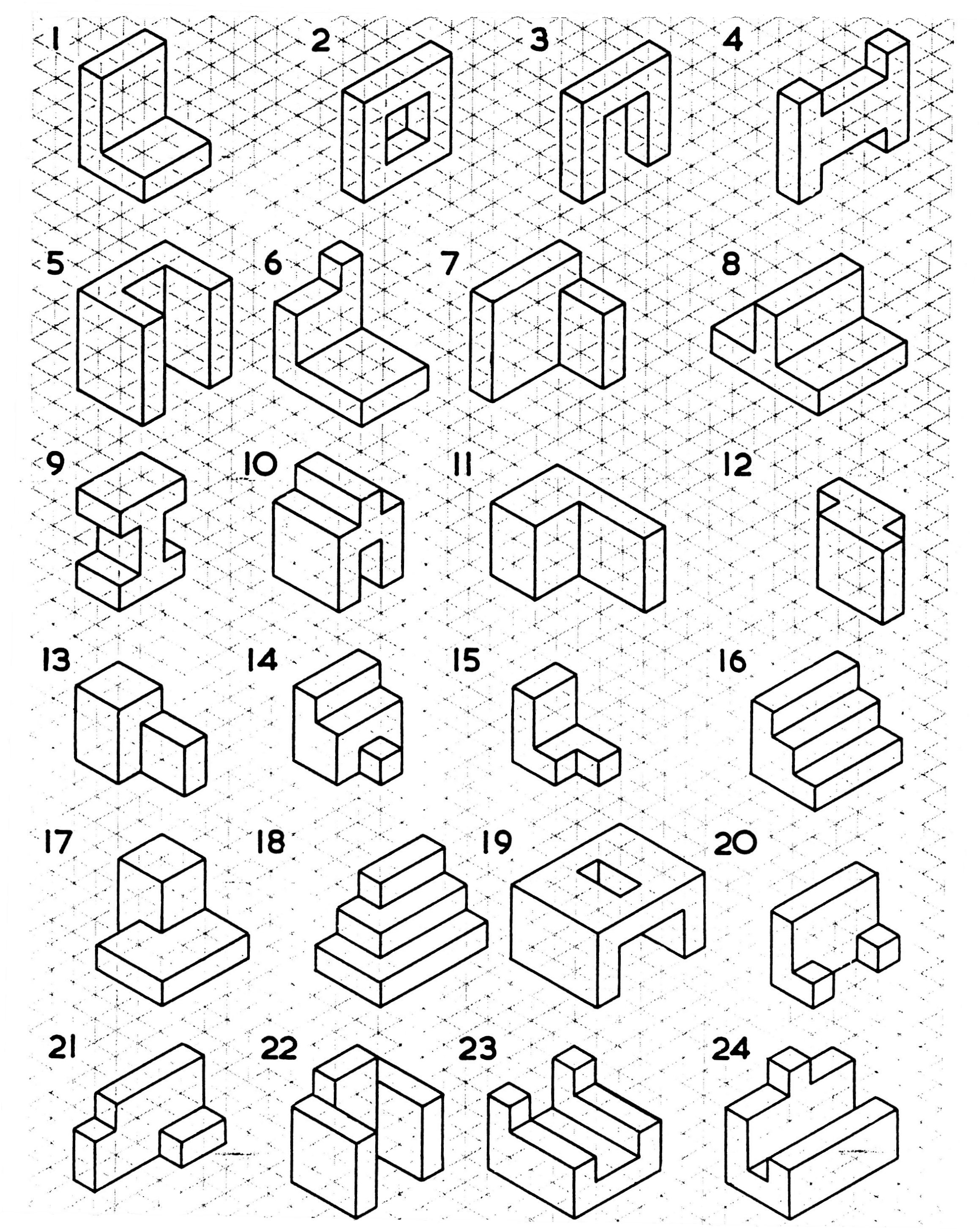
Multiview Drawing Examples at GetDrawings Free download
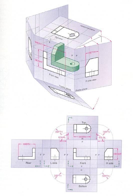
Multiview Drawing Examples at Explore collection
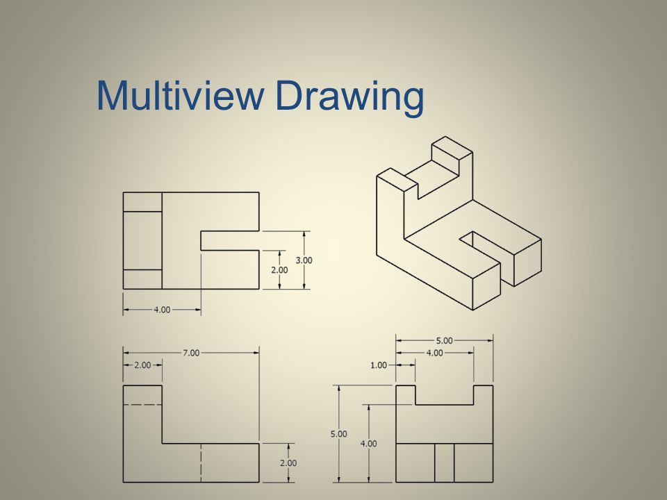
Multiview Drawing at Explore collection of

Multiview Sketching Exercise 2 1 Sketch 2 YouTube
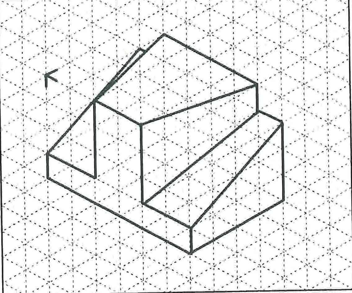
Multiview Drawing Examples at GetDrawings Free download
Multiview Drawing Examples at Explore collection
Multiview Drawing Examples at Explore collection
Multiview Drawing at Explore collection of
Multiview Drawing at Explore collection of
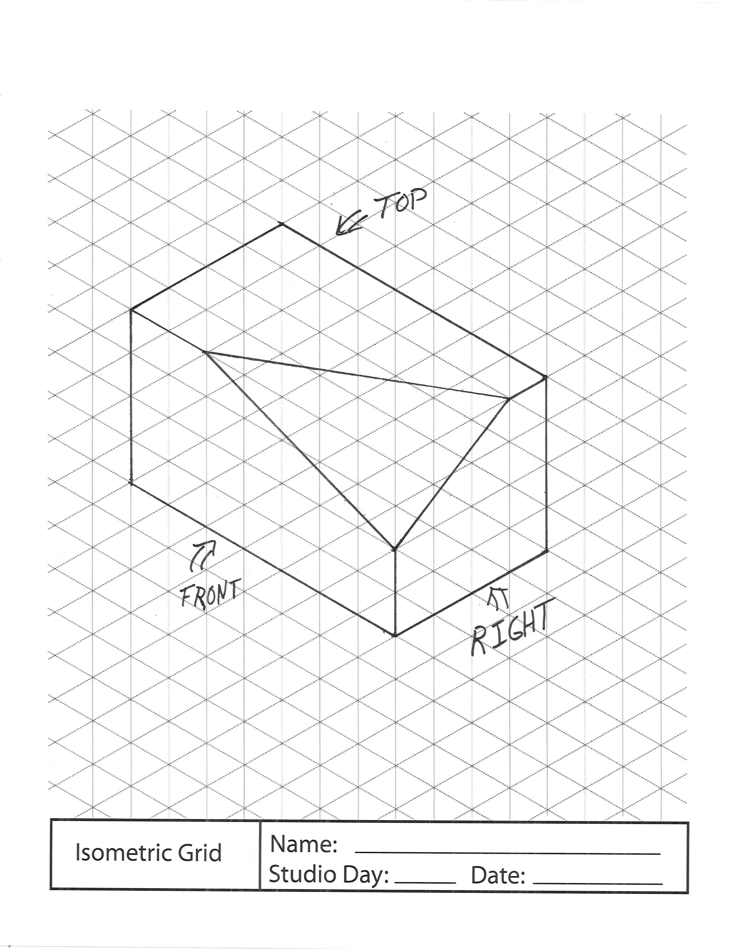
Multiview Drawing Examples at GetDrawings Free download
The General Recommendation Are That Thick Lines Are Twice As Thick As Thin Lines.
The Right Side View Is Projected Onto The Right Profile Plane Of Projection, Which Is A Plane That Is Parallel To The Right Side Of The Object.
Generally Three Views Of An Object Are Drawn, And The Features And Dimensions In Each View Accurately Represent Those Of The Object.
However, You Can Also Use The.
Related Post: