Multiview Drawing Examples
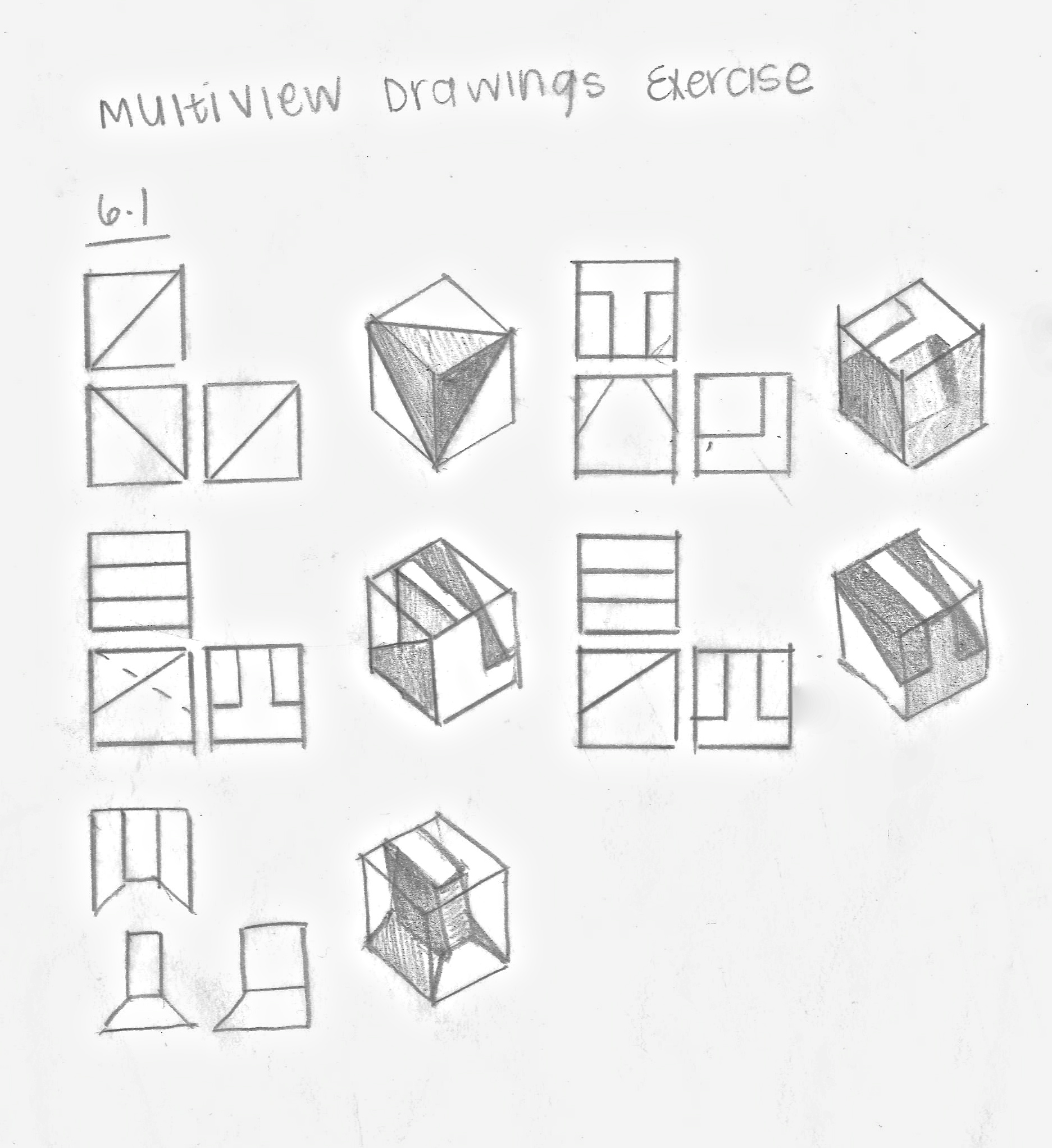
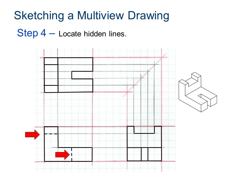
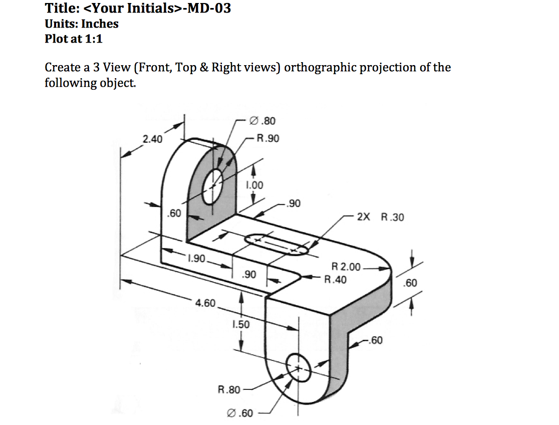
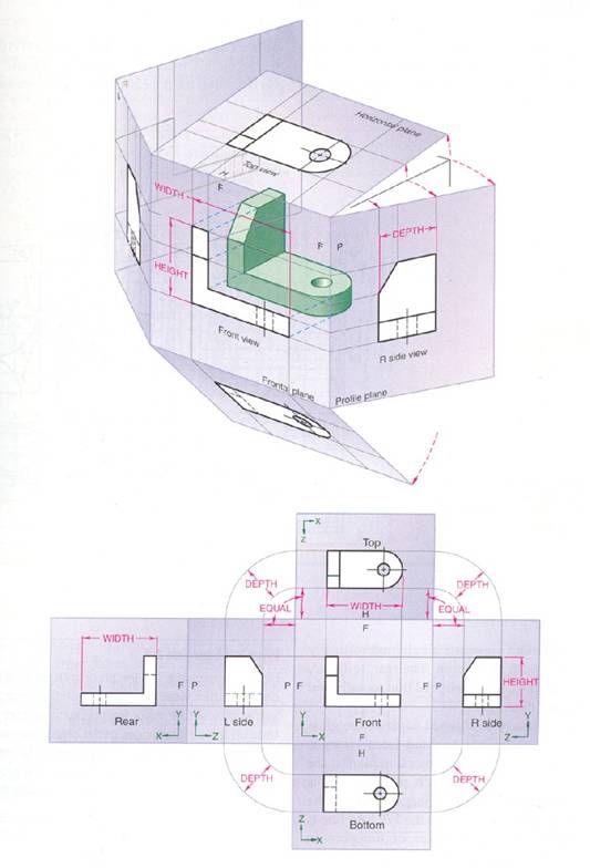
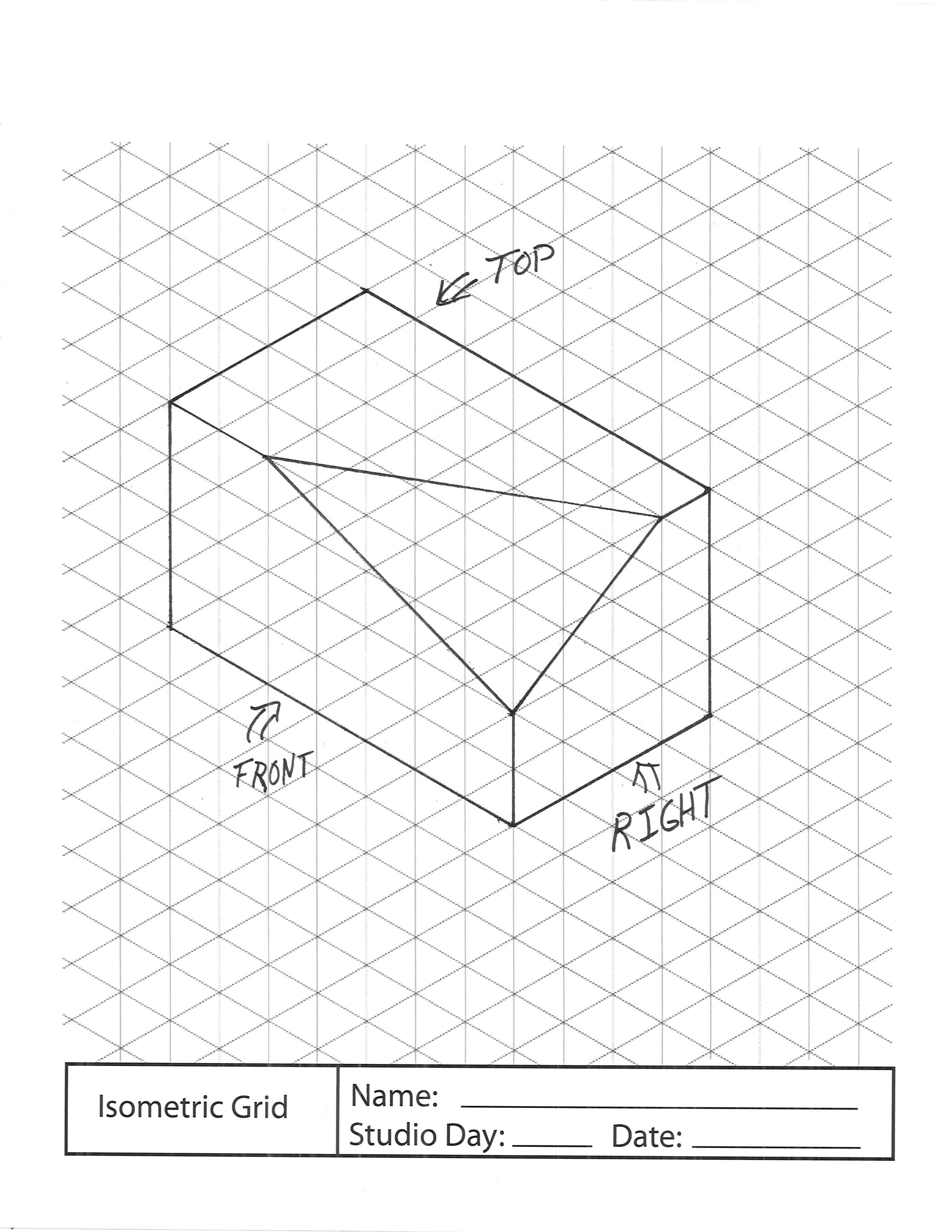
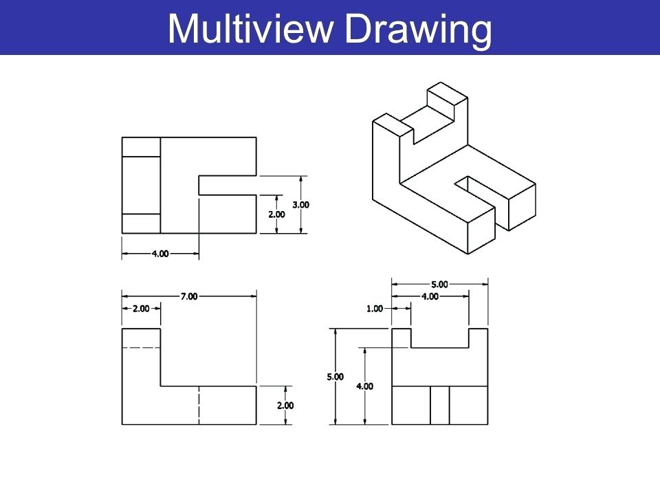
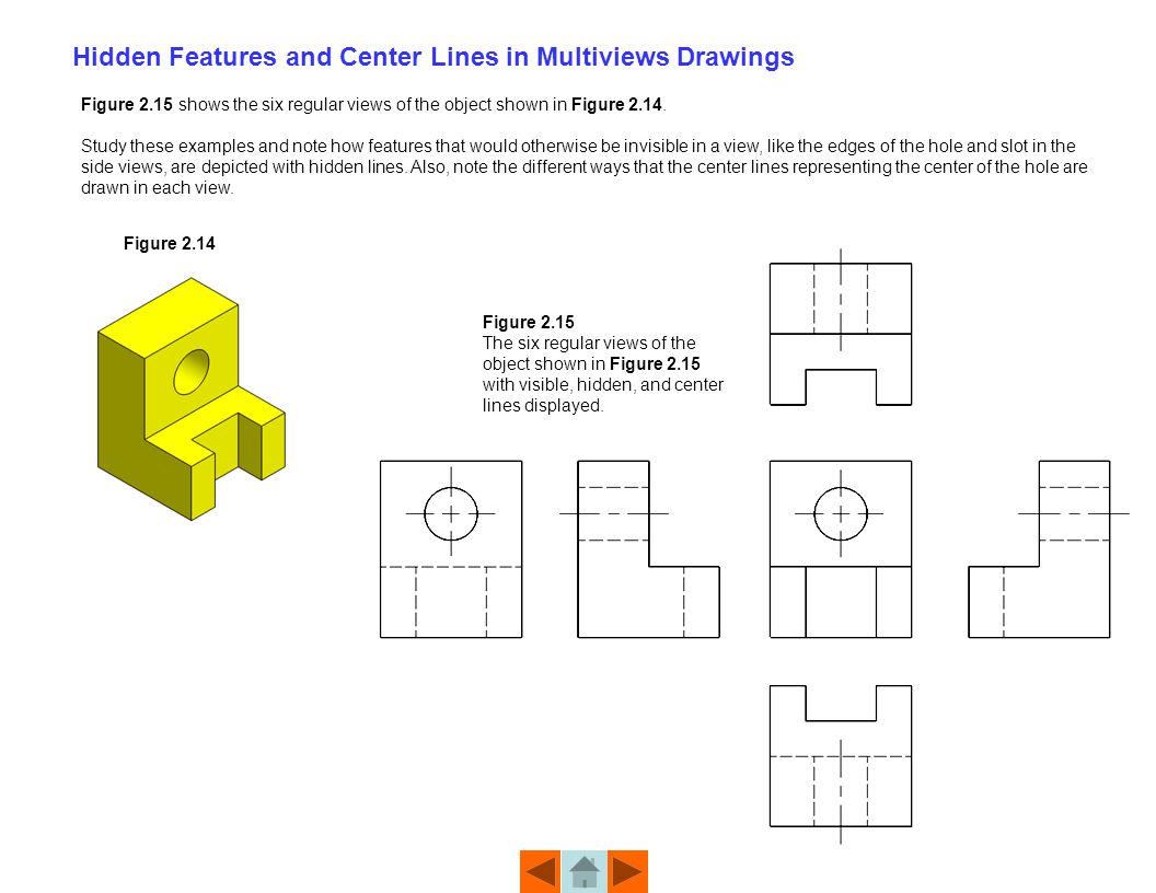
Multiview Drawing Examples - Step 3 set the ucs to world and the view to top. For example, if a multiview drawing was being created from a solid model, the front view is created first as a base view. In the units dialogue box, set the insertion units to inches. For example, rotating one object relative to the other or moving one object along an axis towards the other. Understanding the views you have a total of 6 views you can put in a standard drawing*; Identify frontal, horizontal, and profile planes. Top, bottom, front, back, r side, and l side. But as we saw when we created the isometric drawing, there is distortion. Web describe multiview drawings, the glass box principle, the three standard views, object lines, and hidden lines. Identify limiting elements, hidden features, and intersections of two planes in. Construct 3d models in autocad using multiview drawings. From a 3d pictorial of an object, draw a multiview drawing using the three standard views. When you have completed this module, you will be able to: Chapter 3 included a brief discussion of the characteristics of multiview projection. In this method, orthogonal projection is used to draw and define an object. In this method, orthogonal projection is used to draw and define an object. Web about press copyright contact us creators advertise developers terms privacy policy & safety how youtube works test new features nfl sunday ticket press copyright. Construct 3d models in autocad using multiview drawings. Monge defined a reference system of. Identify limiting elements, hidden features, and intersections of. In the units dialogue box, set the insertion units to inches. Represent lines, curves, surfaces, holes, fillets, rounds, chamfers, runouts, and ellipses in multiview drawings. Explain orthographic and multiview projection. It is called a multiview drawing. For example, rotating one object relative to the other or moving one object along an axis towards the other. An inclined edge, or line, is parallel to a plane of projection, but inclined to the adjacent planes and appears foreshortened in the adjacent views. Identify frontal, horizontal, and profile planes. Web ask question step 1: Along with notes and dimensions, these views provide the information needed to fabricate the part. Gaspard monge's four quadrants and two planes. Step 3 set the ucs to world and the view to top. Explain the importance of multiview drawings. Step 3 complete linetypes erase (minimum) front view orientation right view (not left) top view (not bottom) important detail minimize hidden lines An example of a multiview. Web the advantage of multiview drawings over pictorial drawings is that multiview drawings shows the. Understanding the views you have a total of 6 views you can put in a standard drawing*; Web a multiview drawing usually consists of three views: For the first few examples that follow, sketching techniques will be used because sketching, as opposed to drawing with instruments or cad, is an excellent method for developing visualization skills. The orthographic and/or isometric. When you have completed this module, you will be able to: In this method, orthogonal projection is used to draw and define an object. Along with notes and dimensions, these views provide the information needed to fabricate the part. Web the purpose of a multiview drawing is to fully represent the size and shape of an object using one or. Understanding the views you have a total of 6 views you can put in a standard drawing*; Web for example, the isometric scale is about 18% shorter than true size. Step 1 plan light construction “obvious” detail step 2: For example, rotating one object relative to the other or moving one object along an axis towards the other. Identify limiting. Identify limiting elements, hidden features, and intersections of two planes in. Imagine a cube, 6 equal sides unfolded in the pattern you see in pic 1. Draw isometric drawings on an isometric grid using multiview drawings as a reference. For example, if a multiview drawing was being created from a solid model, the front view is created first as a. In engineering, various methods are used to represent objects. Step 3 complete linetypes erase (minimum) front view orientation right view (not left) top view (not bottom) important detail minimize hidden lines Top, bottom, front, back, r side, and l side. Identify frontal, horizontal, and profile planes. Construct 3d models in autocad using multiview drawings. Along with notes and dimensions, these views provide the information needed to fabricate the part. It controls the scale, orientation, and location of the views projected from it. It is called a multiview drawing. Step 3 set the ucs to world and the view to top. Identify frontal, horizontal, and profile planes. For convenience, the actual dimensions of the object are shown in isometric views and such views are, therefore, called isometric drawings and not isometric projections. Represent lines, curves, surfaces, holes, fillets, rounds, chamfers, runouts, and ellipses in multiview drawings. Web about press copyright contact us creators advertise developers terms privacy policy & safety how youtube works test new features nfl sunday ticket press copyright. Web about press copyright contact us creators advertise developers terms privacy policy & safety how youtube works test new features nfl sunday ticket press copyright. Additionally, the spatial vis software has digitized multiview assignments with automatic grading and instantaneous feedback. Imagine a cube, 6 equal sides unfolded in the pattern you see in pic 1. Identify the six principal views and the three space dimensions. Among these, the engineering drawing or multiview drawing is a major means of communicating the design concept. When you have completed this module, you will be able to: The orthographic and/or isometric views in the drawing are created from the base view. Web for example, the isometric scale is about 18% shorter than true size.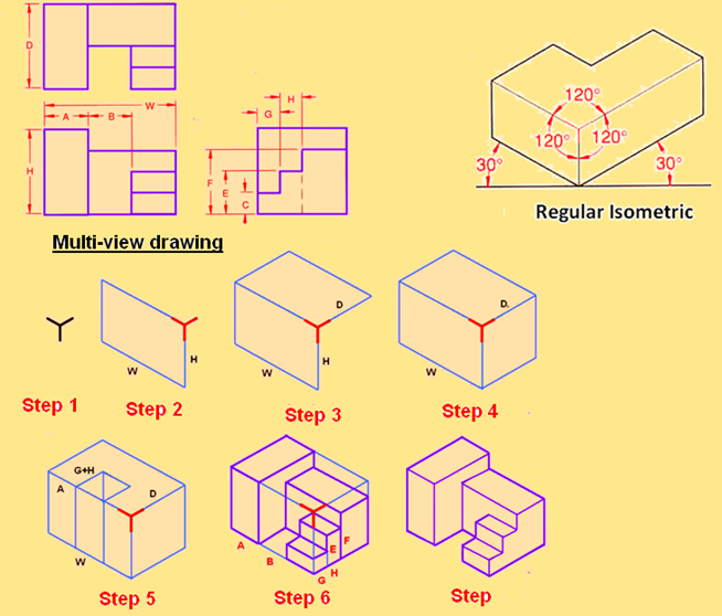
Multiview Drawing Examples at GetDrawings Free download
Multiview Drawing Examples at Explore collection

Multiview Sketch Example YouTube
Multiview Drawing at Explore collection of
Multiview Drawing Examples at Explore collection
Multiview Drawing Examples at Explore collection
Multiview Drawing Examples at GetDrawings Free download
Multiview Drawing Examples at GetDrawings Free download
Multiview Drawing Examples at Explore collection
Multiview Drawing Examples at GetDrawings Free download
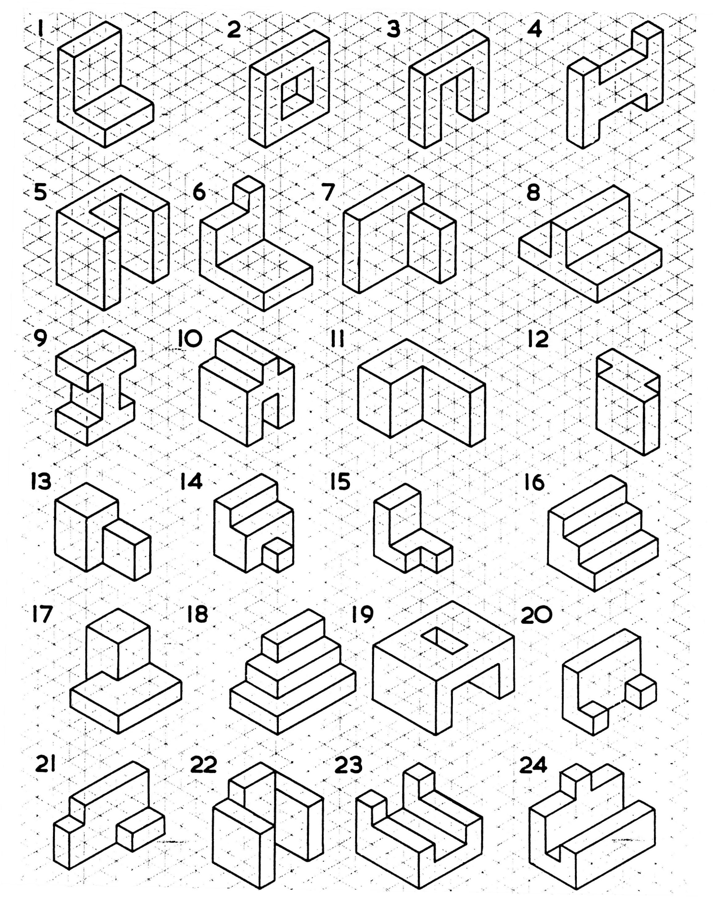
For The First Few Examples That Follow, Sketching Techniques Will Be Used Because Sketching, As Opposed To Drawing With Instruments Or Cad, Is An Excellent Method For Developing Visualization Skills.
Web Ask Question Step 1:
Although In Theory The Part Could Be Placed In Any Orientation, The Views Are Usually Chosen To Coincide With A Natural Symmetry Of The Part—For Example, The Front, Right, And Top Of The Car Shown Above.
Monge Defined A Reference System Of.
Related Post: