Pneumatic Schematic Drawings
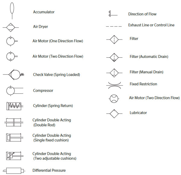
Pneumatic Schematic Drawings - Symbols show the methods of actuation, the number of positions, the flow paths and the number of ports. Here is a brief breakdown of how to read a symbol: Web pneudraw allows you to draw pneumatic circuits quickly and easily. Web here is a complete chart of the basic valves, actuators, combinations and the auxiliary components used in pneumatic logic control circuitry. To start, first locate the origin or source of the pressurized air supply. Its parts, working, and types of pneumatic valves are explained with pictures. Figure 19 provides common symbols used for pumps (hydraulic) and compressors (pneumatic) in fluid power diagrams. Scan through and easily download the one you need. Web hydraulic pumps are shown by solid arrow heads. When it succeeds, it’s invisible. Budweiser air and water system schematics are on the next two slides. Web in this article, we’ll provide a step by step guide for drawing a pneumatic circuit diagram. Symbols representing these valves provide a wealth of information about the valve they represent. This is usually marked as the input on the diagram. With the new online release, it is. Reset showing 1 to 20 of 242 entries display 10 | 20 | 50 | 100 1 2 3 4 5 6 A 5/3 valve schematic will show three blocks describing 3 possible valve functions or positions. Symbols show the methods of actuation, the number of positions, the flow paths and the number of ports. Web here is a complete. When it succeeds, it’s invisible. Web now that we’ve defined it, let’s discuss how to effectively read a pneumatic circuit. To start, first locate the origin or source of the pressurized air supply. Figure 19 fluid power pump and compressor symbols. Budweiser air and water system schematics are on the next two slides. Web outline of pneumatic circuit diagram creation program. To start, first locate the origin or source of the pressurized air supply. Web reading pneumatic schematic symbols the block the block symbolizes the possible valve functions or positions. Click templates > engineering > fluid power > create. The first step in drawing a pneumatic circuit diagram is to familiarize yourself with. This is usually marked as the input on the diagram. Web pneudraw allows you to draw pneumatic circuits quickly and easily. Basic pneumatic circuits air preparation Web pneumatic circuit symbols representing these valves provide detailed information about the valve they represent. Web create fluid power diagrams in visio professional or visio plan 2 to document hydraulic or pneumatic control systems,. Web pneumatic circuit diagrams in practice usually consist of several circuits, that means you have a lots of valves and associated actuators (cylinders, motor). Web here is a complete chart of the basic valves, actuators, combinations and the auxiliary components used in pneumatic logic control circuitry. The previous articles in this series introduced fluids (hydraulic and pneumatic) circuit elements and. Web directional air control valves are the building blocks of pneumatic control. From there, you will need to identify the other components of your circuit. Web create fluid power diagrams in visio professional or visio plan 2 to document hydraulic or pneumatic control systems, such as those used in factory automation systems, heavy machinery, or automobile suspension systems. Web this. This article will describe two example pneumatic systems. In visio 2016 and newer versions: Web directional air control valves are the building blocks of pneumatic control. Web pneudraw allows you to draw pneumatic circuits quickly and easily. Web pneumatic power transmission methods are often the best way to move parts and tooling in industrial machines. Symbols representing these valves provide a wealth of information about the valve they represent. Scan through and easily download the one you need. Budweiser air and water system schematics are on the next two slides. Web pneumatic power transmission methods are often the best way to move parts and tooling in industrial machines. With the new online release, it is. A 5/3 valve schematic will show three blocks describing 3 possible valve functions or positions. Web in this lesson we'll take a look at the schematic symbols for common pneumatic components including but not limited to source elements like motor prime movers, compressors, receivers, filters,. Pneumatic symbols pneumatic symbols only when the design fails does it draw attention to itself;. Web in this lesson we'll take a look at the schematic symbols for common pneumatic components including but not limited to source elements like motor prime movers, compressors, receivers, filters,. Its parts, working, and types of pneumatic valves are explained with pictures. Web directional air control valves are the building blocks of pneumatic control. To read these schematics correctly according to their signal flow, proceed as shown in the animation below. In visio 2016 and newer versions: A 5/2 valve schematic will be illustrated with 2 blocks describing two valve functions or positions. When it succeeds, it’s invisible. With the new online release, it is easier than ever to draw your circuits. Web here is a complete chart of the basic valves, actuators, combinations and the auxiliary components used in pneumatic logic control circuitry. Reset showing 1 to 20 of 242 entries display 10 | 20 | 50 | 100 1 2 3 4 5 6 Symbols show the methods of actuation, the number of positions, the flow paths and the number of ports. Use simplified pneumatic symbols for faster, easier, and more creative pneumatic circuit design. Berry all the symbols you need to design your pneumatic circuit in.dxf format. The previous articles in this series introduced fluids (hydraulic and pneumatic) circuit elements and described three example hydraulic schematic diagrams. Copyright 1985 clippard instrument laboratory. Web pneumatic power transmission methods are often the best way to move parts and tooling in industrial machines.![]()
Pneumatic Circuit Design Airlane Pneumatics Limited

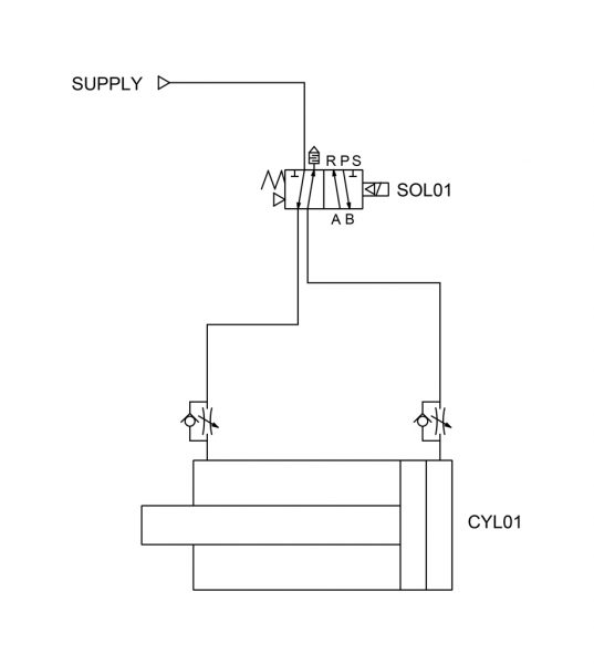
read a circuit diagram
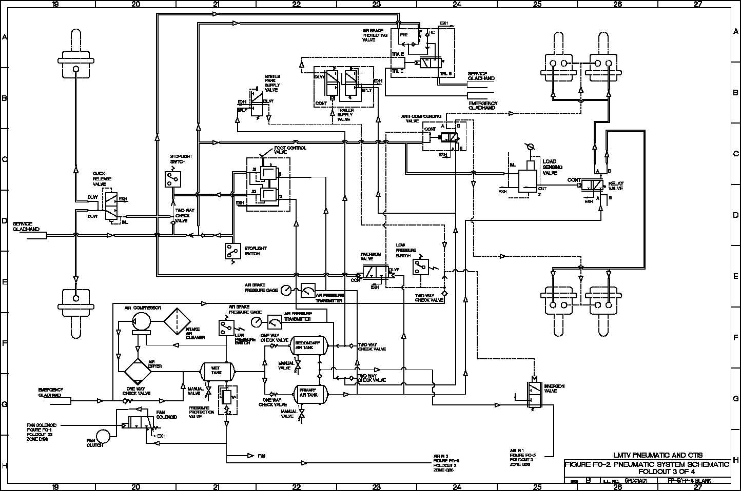
pneumatic system schematic TM92320365202_1363
Pneumatic Circuit Symbols Explained

Pneumatic circuit schematic diagram of multicylinder single
Schematic Diagram Of Pneumatic System Wiring Diagram and Schematics
Schematic Diagram Of Pneumatic System
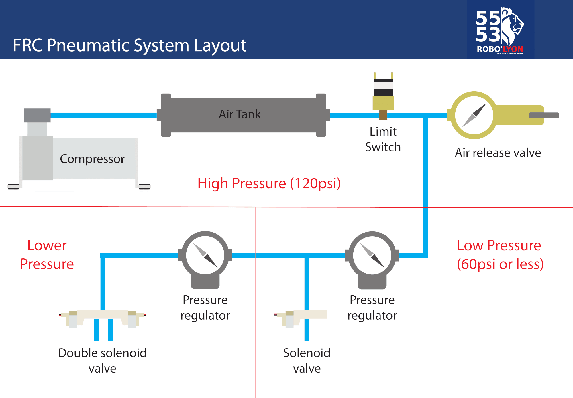
FRC Pneumatic System Diagram Control System Chief Delphi
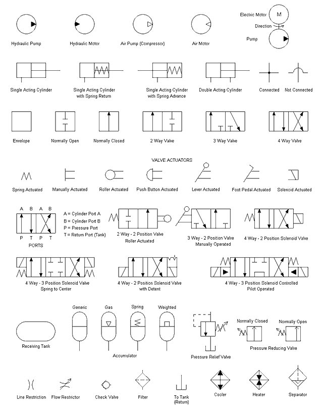
Pneumatic Schematic Symbols

Schematic Diagram Of Pneumatic System Wiring Diagram and Schematics
Web Here Are Four Simple Circuits Of Pneumatic Components That Can Be Used Alone Or As Building Blocks In Larger Systems.
A 5/3 Valve Schematic Will Show Three Blocks Describing 3 Possible Valve Functions Or Positions.
This Article Will Describe Two Example Pneumatic Systems.
Web Mechanical Engineering This Solution Extends Conceptdraw Pro V.9 Mechanical Drawing Software (Or Later) With Samples Of Mechanical Drawing Symbols, Templates And Libraries Of Design Elements, For Help When Drafting Mechanical Engineering Drawings, Or Parts, Assembly, Pneumatic, Basic Rules For Drawing Pneumatic Schematics
Related Post: