Technical Drawing Symbols
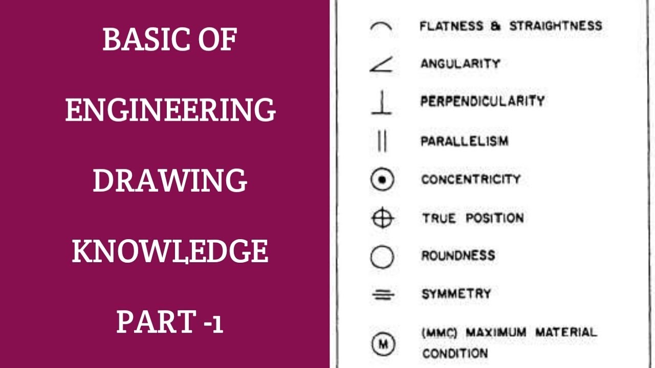
Technical Drawing Symbols - This article provides an overview of technical drawings. Open the project setup of your project Drawing views the first tool in your engineering drawing toolbox is the drawing view. Web basic and common symbols. Views, dimensions, tolerances, symbols, datum’s, feature control frames & title blocks. Web engineering drawing abbreviations and symbols are used to communicate and detail the. In addition, knowledge of the software used to create the drawings is required. Vocabulary and indications on drawings [12] Construction drawings including civil engineering drawings: In addition, this document specifies general rules for the representation of leader and reference lines. This article provides an overview of technical drawings. Web technical drawings convey objective facts, and those facts are represented by the lines and text on the drawing. Do not scale this is standard in engineering diagrams and means that you shouldn’t take measurements from the drawing itself. Web many of the symbols and principles of technical drawing are codified in. Dimensions must be clearly located with extension lines and arrows. Web iso 6433:1981, technical drawings ? Web some common engineering drawing symbols include geometric symbols (circle, square, triangle), symbols for surface finish (roughness, smoothness), symbols for welding (fillet weld, plug weld), symbols for electrical circuits (resistor, capacitor), and symbols for mechanical components (gears, bearings). Text must be printed and legible.. This document establishes the types of lines used in technical drawings (e.g. Web engineering drawing abbreviations and symbols are used to communicate and detail the. Web graphics communications are used in every phase of engineering design starting from concept illustration all the way to the manufacturing phase. This knowledge isn’t just the best way to read an engineering drawing, it’s. Web the symbols work separately, but do not change when trying to use the substitute grip. All dimensions measured in mm the figures in the table at the left of the box are in millimetres. 1.1 symbols permit consistency in the way dimensions and tolerances are specified, and each symbol has a clearly defined meaning. Web product resources understanding technical. All dimensions measured in mm the figures in the table at the left of the box are in millimetres. Web engineering drawing abbreviations and symbols are used to communicate and detail the. Technical drawings for telecommunications and information technology fields: Vocabulary and indications on drawings [12] This document establishes the types of lines used in technical drawings (e.g. Web engineering drawing abbreviations are a set of standardized symbols and abbreviations used on engineering drawings to represent common terms and phrases. Toleranced characteristics and symbols — examples of indication and interpretation The symbols covered in on the following pages are an example of the widespread use of symbols and abbreviations in industry. Mechanical drawing symbols — fluid power equipment. All dimensions measured in mm the figures in the table at the left of the box are in millimetres. Different styles and thicknesses of lines are used to convey different aspects of the object being drawn. No default graphical style is set for the instrument class. Web the symbols work separately, but do not change when trying to use the. The symbols covered in on the following pages are an example of the widespread use of symbols and abbreviations in industry. All dimensions measured in mm the figures in the table at the left of the box are in millimetres. Web currently, we have 16 symbols for geometric tolerances, which are categorized according to the tolerance they specify. This article. Web iso 6433:1981, technical drawings ? Web technical drawings convey objective facts, and those facts are represented by the lines and text on the drawing. Edges of undefined shape ? Mechanical drawing symbols — fluid power equipment library mechanical engineering solution offers 602 commonly used mechanical drawing symbols and objects which are professionally designed and grouped in 8 libraries: General. Web product resources understanding technical drawings involves the ability to interpret the lines and symbols of what you’re looking at. In addition, this document specifies general rules for the representation of leader and reference lines. This document establishes the types of lines used in technical drawings (e.g. In addition, knowledge of the software used to create the drawings is required.. This article provides an overview of technical drawings. Web engineering drawing abbreviations are a set of standardized symbols and abbreviations used on engineering drawings to represent common terms and phrases. Edges of undefined shape ? Web basic and common symbols. Here are more commonly used engineering drawing symbols and design elements as below. Web the standard line types used in technical drawings are. Different styles and thicknesses of lines are used to convey different aspects of the object being drawn. Mechanical drawing symbols — fluid power equipment library mechanical engineering solution offers 602 commonly used mechanical drawing symbols and objects which are professionally designed and grouped in 8 libraries: Views, dimensions, tolerances, symbols, datum’s, feature control frames & title blocks. Web engineering drawing abbreviations and symbols are used to communicate and detail the. Web some common engineering drawing symbols include geometric symbols (circle, square, triangle), symbols for surface finish (roughness, smoothness), symbols for welding (fillet weld, plug weld), symbols for electrical circuits (resistor, capacitor), and symbols for mechanical components (gears, bearings). No default graphical style is set for the instrument class. Open the project setup of your project Web the following is a short list of symbols that normally appear on a technical drawing and need understanding. Do not scale this is standard in engineering diagrams and means that you shouldn’t take measurements from the drawing itself. Radius ‘r’ radius can be for the inside and outside curved surface on the part.
Engineering Drawing Symbols And Their Meanings Pdf at PaintingValley

Technical Drawing Symbols

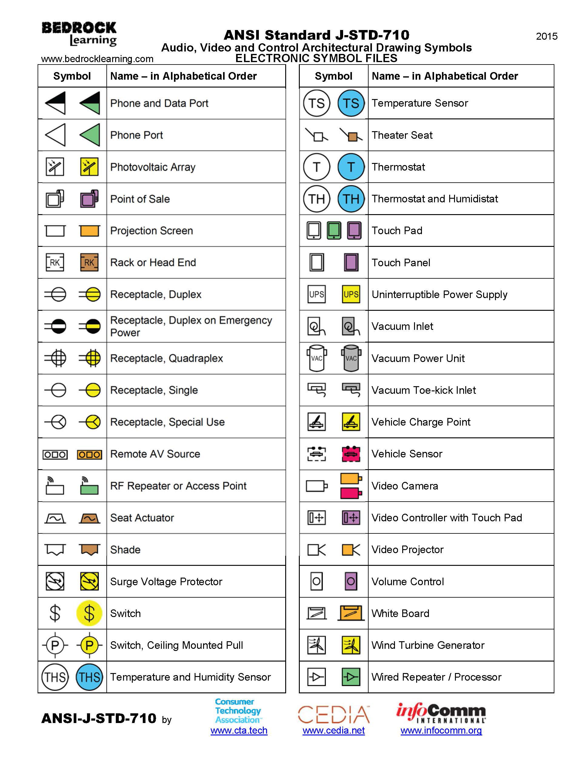
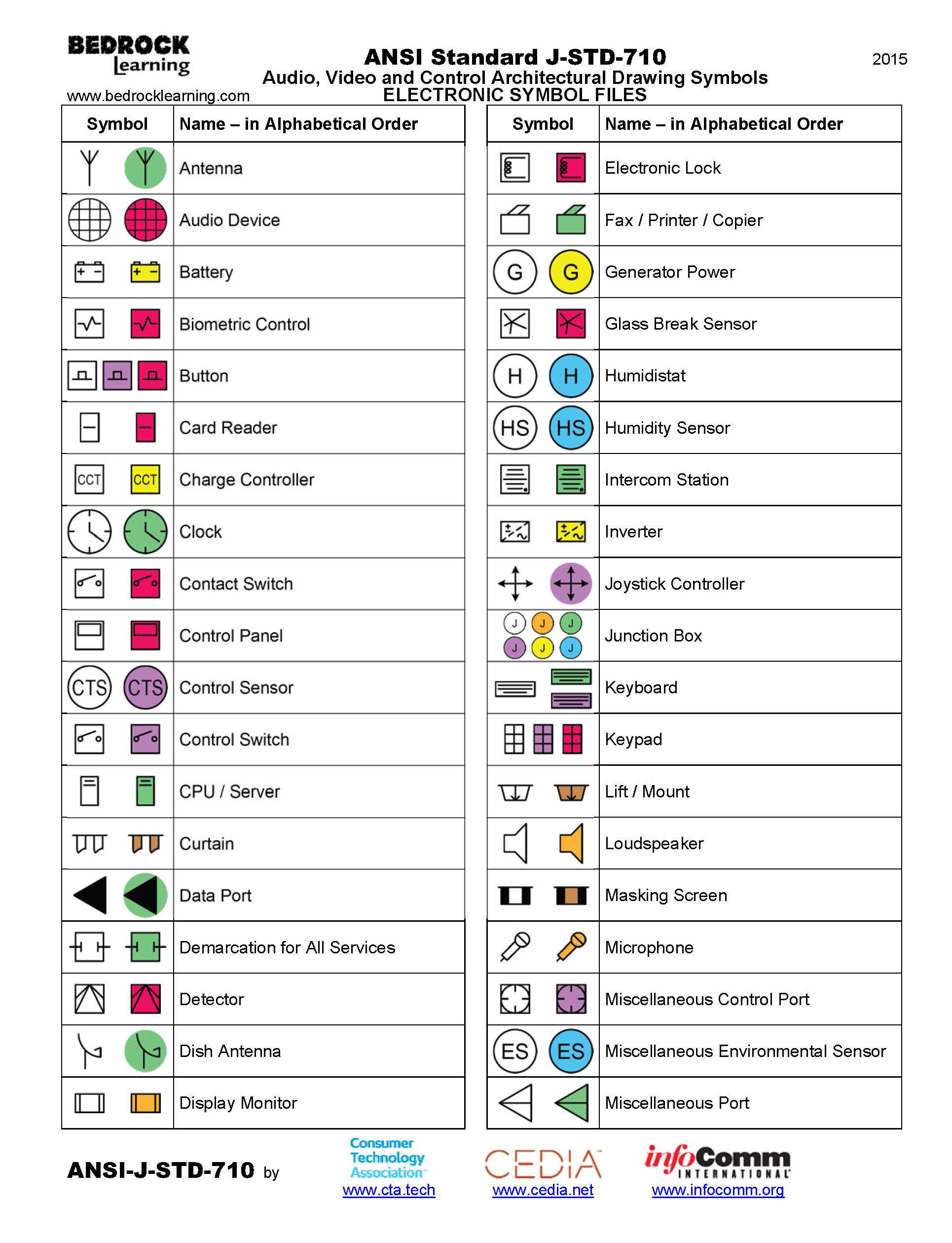
ANSI Standard JSTD710 Architectural Drawing Symbols Bedrock Learning

Engineering Drawing Symbols And Their Meanings Pdf at PaintingValley

Mechanical Engineering Drawing Symbols Pdf Free Download at

Engineering Drawing Symbols And Their Meanings Pdf at PaintingValley

Engineering Drawing Symbols And Their Meanings Pdf at PaintingValley

Important Concept 14+ CAD Drawing Symbols

Mechanical Drawing Symbols

Architectural Drawing Symbols Legend The Architect
Construction Drawings Including Civil Engineering Drawings:
Web Graphics Communications Are Used In Every Phase Of Engineering Design Starting From Concept Illustration All The Way To The Manufacturing Phase.
Dimensions Must Be Clearly Located With Extension Lines And Arrows.
Web Many Of The Symbols And Principles Of Technical Drawing Are Codified In An International Standard Called Iso 128.
Related Post: