Thread Callout Drawing
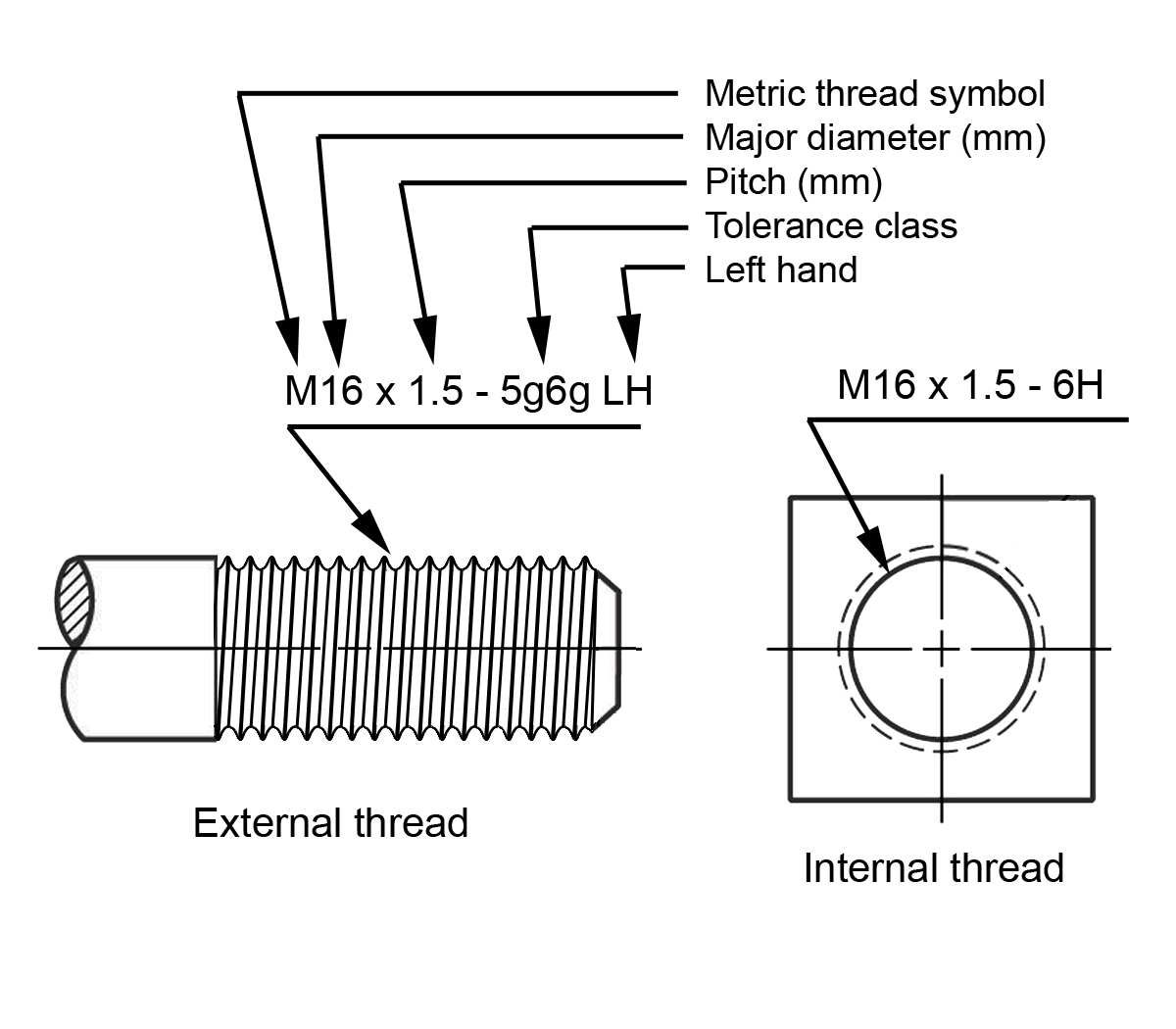
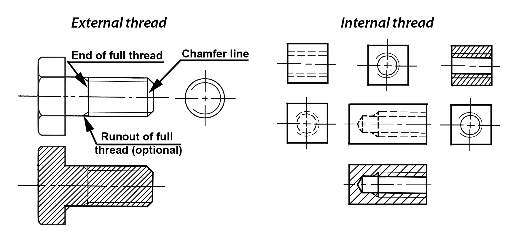
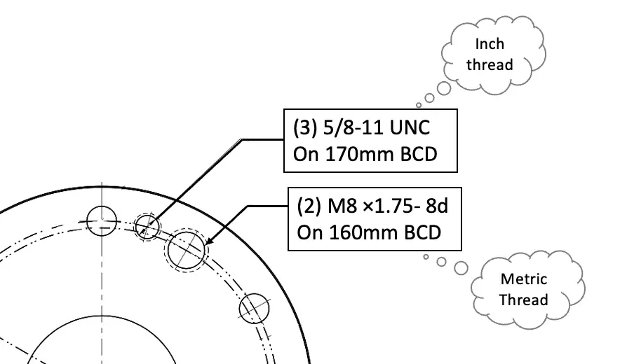
Thread Callout Drawing - Look at the numbers in the callout. Search 'smart dimensioning for simple thread callouts' in the solidworks knowledge base. Web some examples include thread specifications, surface finishes, surface quality, and dimension tolerances. Unified threads (in inches) express diameter as a fixed number #0 through #10, like example a. You have to look for a label on the packaging or on the shelf where you bought the screw. Web i have a drawing with the following callout: Web method 1 using callouts for american screws download article 1 look for a label with the callout printed on it. Notes and references hardware/software configuration platform: Web in drawings, you can add cosmetic thread callouts to external cosmetic threads. If the selection was part of a hole feature, the precision, tolerance, fit class tolerance, and shaft class tolerance values from that feature are automatically applied. Web how can you create a callout for a thread feature in drafting? We are purchasing two locknuts for a bearing application and the vendor lists the thread as a major diameter, the number of threads per inch 5 and class acme 3g. (you insert thread callouts in the cosmetic thread propertymanager, but they appear only in drawing documents.) thread. The tap has a tapper on it, s if i don't tell where to the machinist to stop in depth with the tap, the hole will be over sized, so the ntp fitting will not thread in tight. Web threads are only symbolically represented on drawings; Web specify threads on a 2d drawing with a thread specification callout (aka thread. Web method 1 using callouts for american screws download article 1 look for a label with the callout printed on it. Search 'smart dimensioning for simple thread callouts' in the solidworks knowledge base. The tap has a tapper on it, s if i don't tell where to the machinist to stop in depth with the tap, the hole will be. Web here are the five steps to interpreting thread callout: Web here is my specific question about the two schools of thought, using a typical thread callout. Drag to place the callout. Notes and references hardware/software configuration platform: You use the smart dimension tool to add the callout in a side view or section view of the external thread. The.190 part, however accurate, is not particularly useful. Drag to place the callout. Therefore, thread notes are needed to provide the required information. This handout will focus on the standards of annotation for fasteners, and hole callouts (local notes). Notes and references hardware/software configuration platform: Annotation standardization is provided by the asme y14 series of standards. Search 'smart dimensioning for simple thread callouts' in the solidworks knowledge base. Web i have a drawing with the following callout: On placement the callout appears as “m10x1.0 machine threads”, to change this double click on the text to enter the text editor. The tap has a tapper on. It would be prefereable to not do this manually for every threaded hole. Web method 1 using callouts for american screws download article 1 look for a label with the callout printed on it. For instance if it needs to allow for fine adjustment then class 3 may be appropriate. You have to look for a label on the packaging. Web smart dimensioning for simple thread callouts. Hole callouts and dual dimensions. Web how can you create a callout for a thread feature in drafting? The tap has a tapper on it, s if i don't tell where to the machinist to stop in depth with the tap, the hole will be over sized, so the ntp fitting will not. Web i figure that when i call up a tapped hole, the machinist selects a tap, and the inspector selects a thread gauge. This handout will focus on the standards of annotation for fasteners, and hole callouts (local notes). Web mechanical engineering i.c engines cad/cae/cam in the above tap hole callout, we have given two callouts to understand it in. Web smart dimensioning for simple thread callouts. Web how can you create a callout for a thread feature in drafting? Web some examples include thread specifications, surface finishes, surface quality, and dimension tolerances. Unified threads (in inches) express diameter as a fixed number #0 through #10, like example a. Web here is my specific question about the two schools of. Web how can you create a callout for a thread feature in drafting? The nominal holes diameter will be shown to the two places decimal. We can visualize each hole’s tolerance zone as a cylinder with a diameter of ø.016 inches, having an axis perfectly perpendicular to datum plane a. Web when a thread is called out on a drawing, the information will include the nominal size (diameter) and may include either the threads per inch or thread pitch, depending on whether inch or metric threads are being used. If the selection was part of a hole feature, the precision, tolerance, fit class tolerance, and shaft class tolerance values from that feature are automatically applied. Web a thread callout is also inserted if the drawing document is in ansi standard. I've checked the drafting preferences for hole callouts and thread class does not seem to be an option that i can select. The difference is one group says also call out diameter of the hole to be drilled to prepare for tapping, second group says don't include diameter of the hole, the thread callout handles it all. Web smart dimensioning for simple thread callouts. The tap has a tapper on it, s if i don't tell where to the machinist to stop in depth with the tap, the hole will be over sized, so the ntp fitting will not thread in tight. You use the smart dimension tool to add the callout in a side view or section view of the external thread. The two dimensions are 15.745 and 13.339 inches. Therefore, thread notes are needed to provide the required information. Web mechanical engineering i.c engines cad/cae/cam in the above tap hole callout, we have given two callouts to understand it in both metric and inch systems. It would be prefereable to not do this manually for every threaded hole. Web how do you call out a npt thread length on a drawing?
Dimensioning threaded fasteners Engineering Design McGill University

How to prepare a technical drawing for CNC machining 3D Hubs

Dimensioning threaded fasteners Engineering Design McGill University

How to Draw Threaded Hole in Autocad 2d Adkins Fricaunt

Dimensioning threaded fasteners Engineering Design McGill University

How to Read Screw Thread Designation? ExtruDesign

Using Cosmetic Threads in SOLIDWORKS Parts and Drawings

How to design an external & internal thread (simplified) and then draw

PPT Threads and Fasteners PowerPoint Presentation, free download ID

Basics on Threads Get It Made
Web Specify Threads On A 2D Drawing With A Thread Specification Callout (Aka Thread Hole Callout) For Metric Sizes, Specify Size With The Thread Pitch (Diameter X Pitch In Mm);
The Callout That Will Be Used On Kress Engineering Drawings Will Be As Follows:
The.190 Part, However Accurate, Is Not Particularly Useful.
Web In Drawings, You Can Add Cosmetic Thread Callouts To External Cosmetic Threads.
Related Post: