Valve Symbols For Drawings
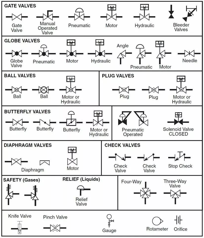
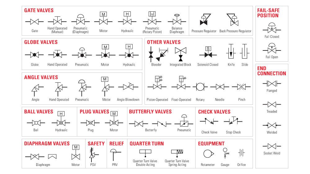
Valve Symbols For Drawings - Figure 1 shows the symbols that depict the major valve types. They include the valve symbol with modifier and the generic valve symbols. These illustrations, commonly referred to as piping and instrumentation diagram (p&di) symbols, may vary slightly between organizations but similar sketches are used to identify types and position of valves. The flow path is shown by small arrows beside the symbol. These pfd symbols are assembled on the drawing in a manner that. Web a piping and instrumentation diagram (p&id) is a graphic representation of a process system that includes the piping, vessels, control valves, instrumentation, and other process components and equipment in the system. Web in this article, we highlight some of the most common p&id valve symbols, process lines, end connections and other vital components. A diaphragm valve is a type of valve that uses a diaphragm to control the flow of fluid. Web valve symbols valves are used to control the direction, flow rate, and pressure of fluids. Symbols are shown in black lines. Web a piping and instrumentation diagram (p&id) is a graphic representation of a process system that includes the piping, vessels, control valves, instrumentation, and other process components and equipment in the system. Figure 1 shows the symbols that depict the major valve types. In such cases, information concerning the valve type may be conveyed by the component These pfd symbols. Web in each process and instrumentation diagram, valves have specific symbols that make them easy to. Figure 3 shows the various symbols used in multiport valves. Web edrawmax includes standard sets of symbols depicting mechanical equipment, piping, piping components, valves, equipment drivers, instrumentation, and controls. Web these symbols include: While there is some variation, examples of the standard symbols for. Figure 1 shows the symbols that depict the major valve types. Angle blowdown valve angle globe valve angle valve angle valve hand operated auto circulation valve back pressure regulator balanced diaphragm gate valve ball valve ball valve normally closed bleeder valve butterfly valve check valve 01 check valve 02. Symbols are shown in black lines. Web each p&id has its. The operation of valves can either be automatic, manual, pneumatic (diaphragm), motor, hydraulic, solenoid, pneumatic (rotary piston), balance, and more. A multitude of valve types and designs safely accommodate a wide variety of industrial applications. Figure 1 shows the symbols that depict the major valve types. (in other cutaway graphics, springs are sometimes drawn with diagonal lines connecting the dots,. How to draw a p&id. Web know your valve symbols. Web edrawmax includes standard sets of symbols depicting mechanical equipment, piping, piping components, valves, equipment drivers, instrumentation, and controls. It should be noted that globe and gate valves will often be depicted by the same valve symbol. Downloadable pdf of valve, actuator and other popular p&id symbols. Web the symbology for the identification of the measurement and control instrumentation on the flow and process diagrams and on the p&id (piping & instrument diagram), commonly called p&i (piping & instrumentation), is generally compliant with the standard isa (instrumentation society of automation) identified as s.5, that is composed. The complex world of process and instrumentation drawings (p&ids) is replete. Symbols for operations are in the graphic below. Knowing your valve symbols will make your life much easier when it comes time to decipher your pipe and system diagram. Web learn about types of valve symbols used in p&id and iso drawing. Web in each process and instrumentation diagram, valves have specific symbols that make them easy to. In such. These pfd symbols are assembled on the drawing in a manner that. Web these symbols include: Web know your valve symbols. Symbols are shown in black lines. Web piping and instrumentation diagrams (p&ids) use specific symbols to show the connectivity of equipment, sensors, and valves in a control system. A multitude of valve types and designs safely accommodate a wide variety of industrial applications. Lighter lines show connected pipe, and are not parts of the symbols. (in other cutaway graphics, springs are sometimes drawn with diagonal lines connecting the dots, representing the coil of the spring.). Web piping and instrumentation diagrams (p&ids) use specific symbols to show the connectivity. The operation of valves can either be automatic, manual, pneumatic (diaphragm), motor, hydraulic, solenoid, pneumatic (rotary piston), balance, and more. How to draw a p&id. Furthermore, the symbols can indicate the valve operation. Web the symbology for the identification of the measurement and control instrumentation on the flow and process diagrams and on the p&id (piping & instrument diagram), commonly. Furthermore, the symbols can indicate the valve operation. These symbols can represent actuators, sensors, and controllers and may be. A piping and instrumentation diagram (p&id) includes symbols for ball valves, communication lines, vessels and other components. Web piping and instrumentation diagrams (p&ids) use specific symbols to show the connectivity of equipment, sensors, and valves in a control system. Web as the picture shows below, the valve symbol library has collected various valves types, so as to satisfy different drawing needs. Use our valve product selection guide to. Web a piping and instrumentation diagram (p&id) is a graphic representation of a process system that includes the piping, vessels, control valves, instrumentation, and other process components and equipment in the system. (in other cutaway graphics, springs are sometimes drawn with diagonal lines connecting the dots, representing the coil of the spring.). Angle blowdown valve angle globe valve angle valve angle valve hand operated auto circulation valve back pressure regulator balanced diaphragm gate valve ball valve ball valve normally closed bleeder valve butterfly valve check valve 01 check valve 02. The complex world of process and instrumentation drawings (p&ids) is replete with a range of valve diagrams and symbols. Valve symbols valves are used to control the direction, flow rate, and pressure of fluids. While each of these symbols has several variables for their different types of valves, these main category symbols will help get a general understanding. Such as ball valve, plug valve, refile valve, gate valve, check valve, butterfly valve. Symbols are shown in black lines. Web valve symbols for operation. A multitude of valve types and designs safely accommodate a wide variety of industrial applications.
Valve Symbols in P&ID Ball Valve, Relief Valve and more

Control Valve Pneumatic Symbols Free CAD Block And AutoCAD Drawing

Valves Symbols used in P&ID and Piping Isometric drawings YouTube

Types Of Valves, Their Functions And Symbols Engineering Discoveries
Valve symbols
check valve symbols on drawings Symbols engineering process diagram
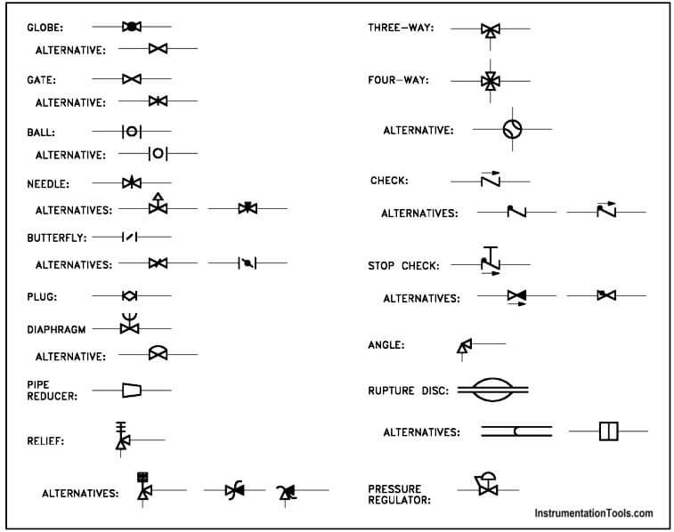
Piping and Instrumentation Symbols Instrumentation Tools
The Most Common Control Valve Symbols on a P&ID Kimray

Valve Symbols Free CAD Block And AutoCAD Drawing

Drawing Symbol for Valves and Joints Engineer Diary
Figure 1 Shows The Symbols That Depict The Major Valve Types.
Downloadable Pdf Of Valve, Actuator And Other Popular P&Id Symbols.
Web The Symbology For The Identification Of The Measurement And Control Instrumentation On The Flow And Process Diagrams And On The P&Id (Piping & Instrument Diagram), Commonly Called P&I (Piping & Instrumentation), Is Generally Compliant With The Standard Isa (Instrumentation Society Of Automation) Identified As S.5, That Is Composed.
Web Isometric Drawing Symbols For Valves.
Related Post: