Hydraulic Drawing Symbols
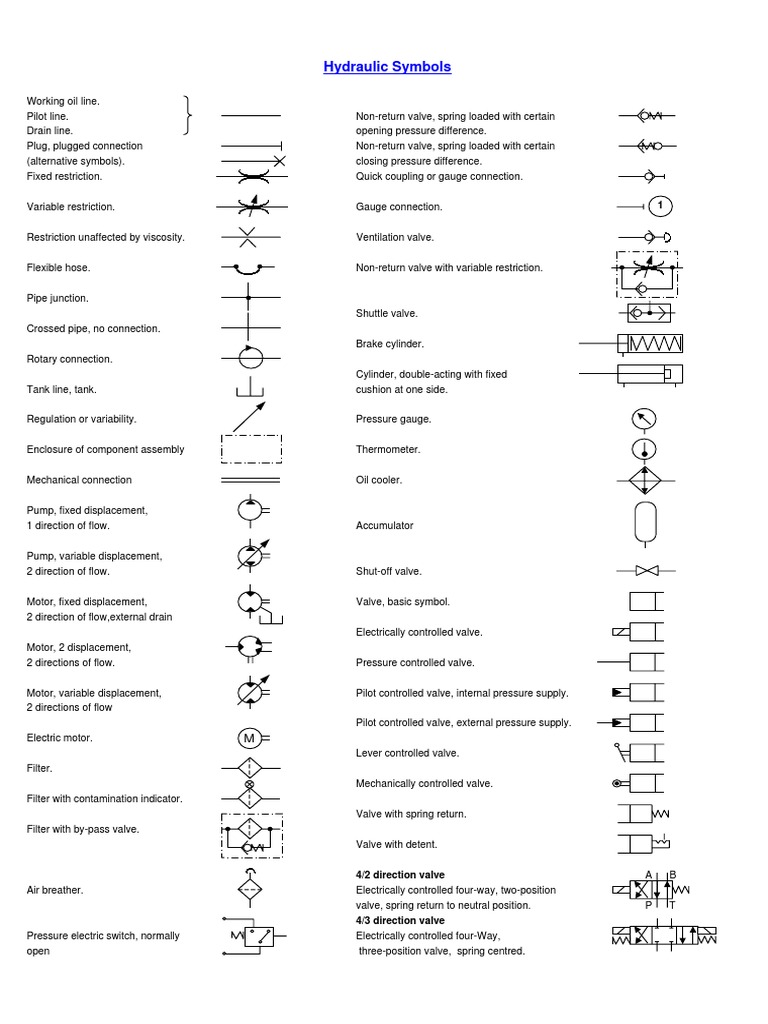
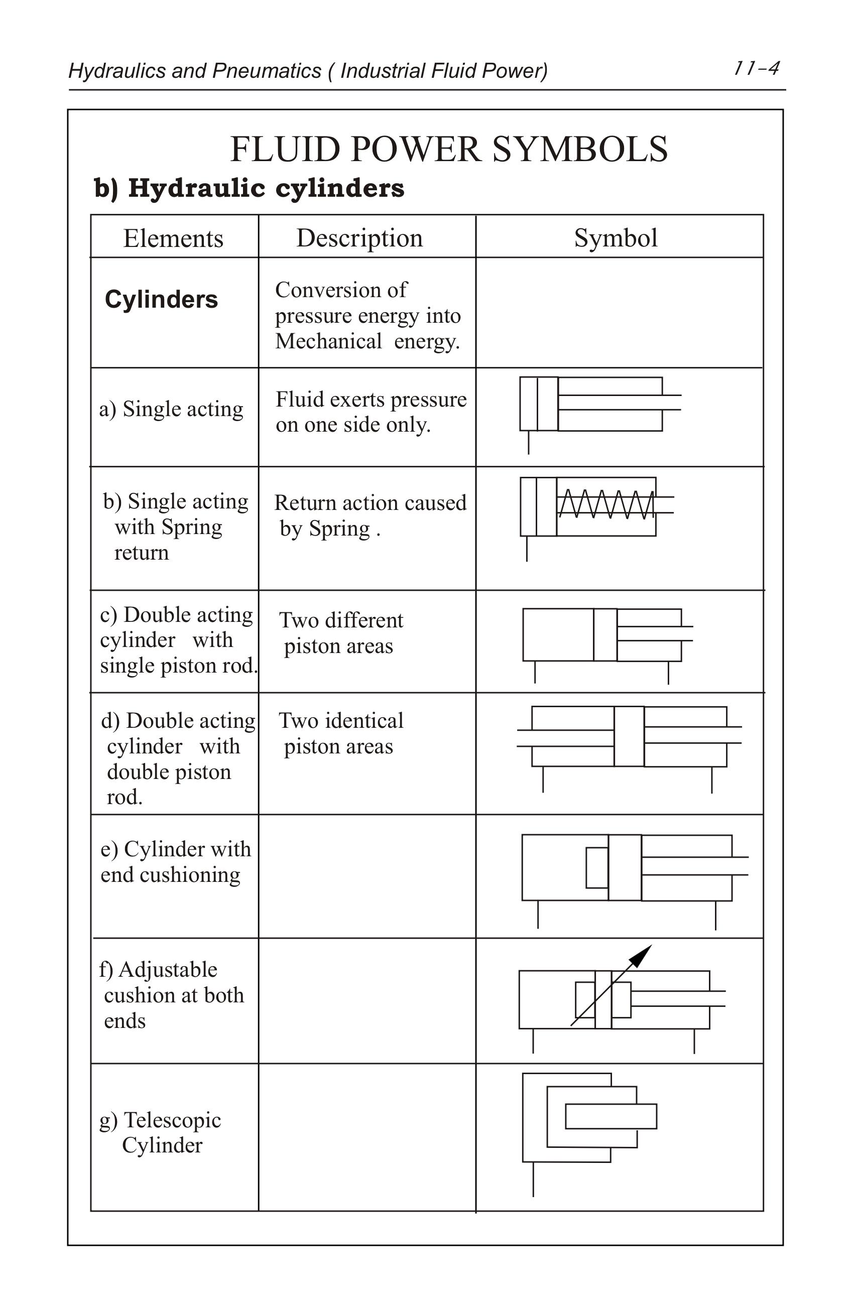
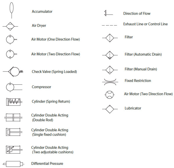
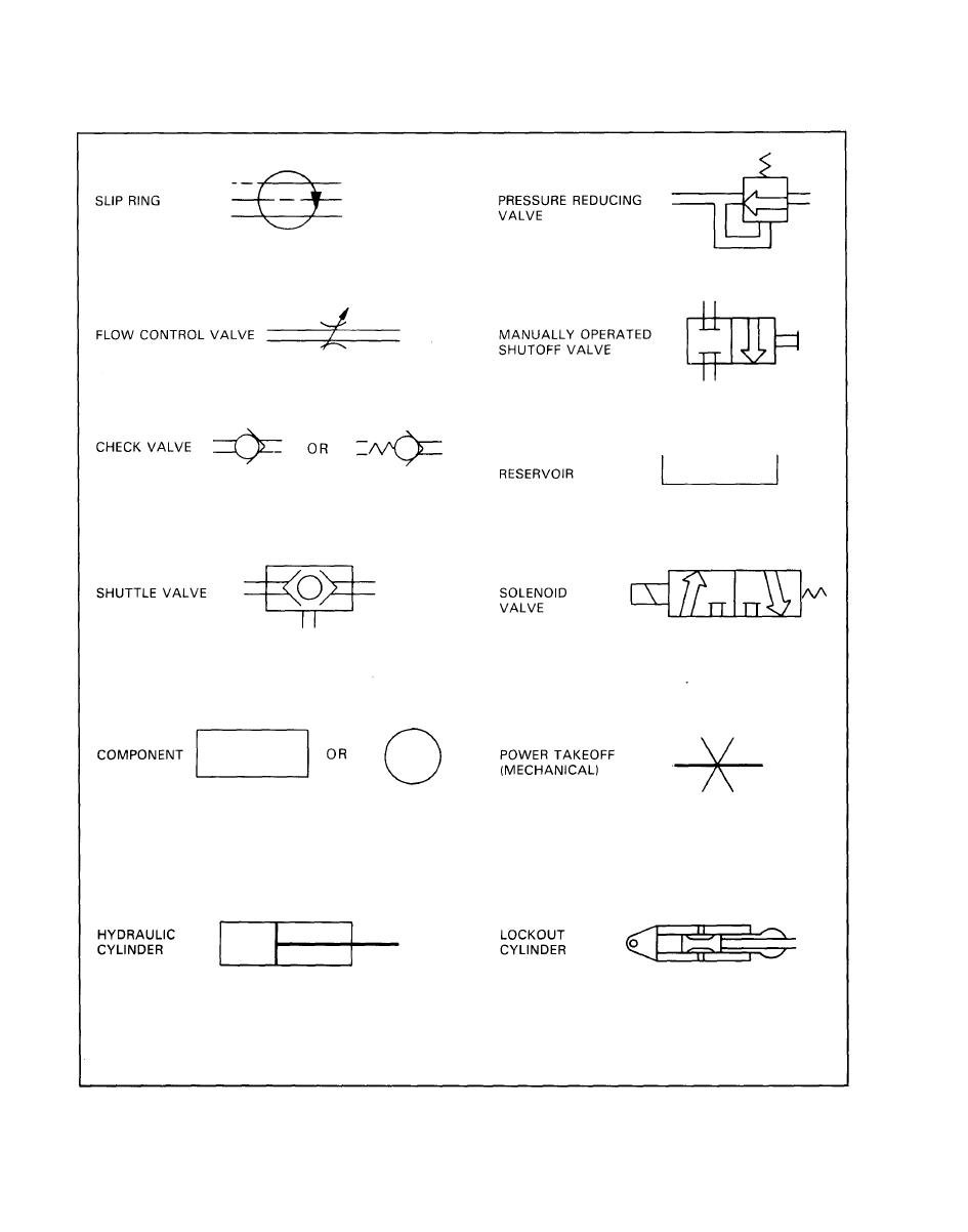
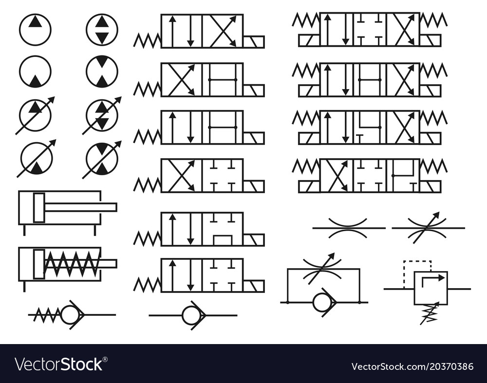
Hydraulic Drawing Symbols - Web here in this article we will learn five most used iso hydraulic symbols and their practical meanings: Web fluid actuators are used to convert fluid energy into mechanical linear motion. Web hydraulic & pneumatic symbols. Triangular arrows represent the direction fluid takes in the pump or motor. Other common symbols you need to know are: Cylinders are drawn as rectangles with lines in the center to represent the piston, and lines through the ends to represent the rod. Web hydraulic symbols provide a clear representation of the function of each hydraulic component. Web if you experience any problems with the site, please contact pete hoffman immediately so corrections can be made. Web the lines that represent hydraulic hoses, pipes, and tube assemblies are an essential part of every schematic. Web engineering drawings for hydraulics have a few symbols and practices that distinguish them from a standard engineering drawing. Web the complexity of these components are difficult to represent fully, so a family of graphic symbols have been developed to represent fluid power components and systems on schematic drawings. What is the do not scale note? The basic drawn lines, cylinder symbols, ejector symbols, and the do not scale note are just a handful of items that are particular. Laying each symbol out on the page in the same sequence the components are used in the circuit allows people to understand the complete function of the hydraulic equipment. Web engineering drawings for hydraulics have a few symbols and practices that distinguish them from a standard engineering drawing. Web the complexity of these components are difficult to represent fully, so. The basic line is a solid line that represents a working pressure hose or tube. Web here in this article we will learn five most used iso hydraulic symbols and their practical meanings: Web hydraulic schematics use a wide range of symbols to represent different parts and connections. In addition, colors can be added to indicate purpose of the line.. Web symbols for hydraulic systems are for functional interpretation and comprise one or more function symbols. Web fluid actuators are used to convert fluid energy into mechanical linear motion. Pete can be reached on campus, via email at [email protected] or by phone at 1.800.362.3322 ext 2727. Web types of symbols commonly used in drawing circuit diagrams for fluid power systems. Web hydraulic & pneumatic symbols. Web hydraulic symbols provide a clear representation of the function of each hydraulic component. Hoses, pipes and tube assemblies twitter linkedin if you are going to be designing, implementing or maintaining hydraulic systems, the ability to understand schematics is an essential skill you will need to develop Web a hydraulic circuit represents all the hydraulic. This is called the hydraulic reservoir. Web engineering drawings for hydraulics have a few symbols and practices that distinguish them from a standard engineering drawing. Short dashed lines are return/drain/tank lines. In addition, colors can be added to indicate purpose of the line. Hoses, pipes and tube assemblies twitter linkedin if you are going to be designing, implementing or maintaining. Web hydraulic valves symbols including 3/2 ways, 5/2 ways and other devices used in the design of hydraulic circuit drawings. Web hydraulic schematics use a wide range of symbols to represent different parts and connections. Familiarize yourself with these symbols by consulting books or manuals that describe what each symbol stands for. Web the complexity of these components are difficult. Web an introduction to hydraulic symbols: It's the pipes or hoses between components and the flow channels within components. Web we only touched on the basic elements of hydraulic symbols to be aware of and what they look like on hydraulic schematics. For port identification and operator marking see iso 9461 (hydraulic) or bs iso 5599 (pneumatic). Web hydraulic symbols. Next, pay attention to the arrows. This is called the hydraulic reservoir. Familiarize yourself with these symbols by consulting books or manuals that describe what each symbol stands for. What is the do not scale note? Web a hydraulic circuit represents all the hydraulic components in a system. Web h draulics online basic symbols pressure or return line pilot line two or more functions in one unit flexible hose union closed conneci'ion direction of movement direction of rotation regulation possible electric solenoids working in opposite directions direction of. Web hydraulic schematics use a wide range of symbols to represent different parts and connections. It's the pipes or hoses. These symbols are fully explained in the usa standard drafting manual (ref. Cylinders are drawn as rectangles with lines in the center to represent the piston, and lines through the ends to represent the rod. Web the basics of hydraulic symbology are quite easy, but i’ve only scratched the surface. For more information about reading hydraulic and pneumatic circuit diagrams, read the next article in this series which describes sample hydraulic circuits, or contact your valmet representative. Pete can be reached on campus, via email at [email protected] or by phone at 1.800.362.3322 ext 2727. 1.1.1pictorial symbols are very useful for showing the interconnection of components. The complexity of these components are difficult to represent fully, so a family of graphic symbols have been developed to represent fluid power components and systems on schematic drawings. Web types of symbols commonly used in drawing circuit diagrams for fluid power systems are pictorial, cutaway, and graphic. This is called the hydraulic reservoir. This will make it much easier to interpret the schematic. Web fluid actuators are used to convert fluid energy into mechanical linear motion. The basic line is a solid line that represents a working pressure hose or tube. Web hydraulic & pneumatic symbols. This includes the arrangement of the components and the behavior of the system as a whole in a universally accepted symbolic manner. Web hydraulic circuits can be comprised of an infinite combination of cylinders, motors, valves, pumps and other equipment connected via hydraulic pipes and tubes. Web hydraulic schematics use a wide range of symbols to represent different parts and connections.Hydraulic Symbols
Hydraulics Pneumatics Symbols
Hydraulic Valve Symbols Autocad energyfabric
Pneumatic Circuit Symbols Explained
HYDRAULIC SYMBOLS
Set hydraulic symbols Royalty Free Vector Image
Hydraulic & Electric Symbols Valve Technology

A guide to common hydraulic symbols EngineeringClicks

Valve Operator Pneumatic Symbols Free CAD Block And AutoCAD Drawing

Mariners Repository Hydraulics Part 1 Direction Control Valves
Web H Draulics Online Basic Symbols Pressure Or Return Line Pilot Line Two Or More Functions In One Unit Flexible Hose Union Closed Conneci'ion Direction Of Movement Direction Of Rotation Regulation Possible Electric Solenoids Working In Opposite Directions Direction Of.
The Following List Is Contains Hydraulic Schematic Symbols To.
Web Hydraulic Cylinders Convert Fluid Power To Linear Mechanical Power.
Web The Complexity Of These Components Are Difficult To Represent Fully, So A Family Of Graphic Symbols Have Been Developed To Represent Fluid Power Components And Systems On Schematic Drawings.
Related Post: